


.png)


Across every sector of heavy fabrication — from oil & gas valve bodies and excavator bucket assemblies to pressure vessel nozzle connections and pipeline elbows — the welding positioner is the equipment that makes the difference between a difficult, all-position weld and a fast, flat-position weld. By tilting and rotating the workpiece to present any joint in the optimum welding orientation, a positioner eliminates positional welding, reduces operator fatigue, increases arc-on time, and delivers consistently higher-quality welds.
Unlike a welding rotator — which handles cylindrical workpieces through continuous horizontal-axis rotation — a welding positioner grips the workpiece on a faceplate or between centres and can tilt, rotate, and reposition it in any orientation. This makes positioners the correct choice for asymmetric, flanged, or complex-geometry components that cannot be supported on simple turning rolls.
This guide covers all four major positioner types: the welding turning table, the hydraulic positioner, the head and tail stock positioner, and the L-type welding positioner — together with full application, specification, and selection guidance aligned with AWS, ASME, and EN ISO 3834 requirements.
Related Search Terms

1. What Is a Welding Positioner?
A welding positioner is a motorised workholding system that rotates and/or tilts a workpiece to present any weld joint in the flat (1G/1F) or horizontal-fixed (2G/2F) position — the two most productive and consistent welding orientations. Unlike manual repositioning by crane (which requires stopping welding, rigging, and re-setting up), a positioner enables continuous, in-cycle repositioning without interrupting the welding process.
A welding positioner differs from a welding rotator in a fundamental way: a rotator supports a cylindrical workpiece from below on turning rolls and rotates it about its own axis — suitable for pipes, vessels, and tanks. A positioner grips the workpiece on a faceplate, between chuck jaws, or between headstock and tailstock centres — making it suitable for any geometry, including flanged assemblies, valve bodies, structural frames, buckets, elbows, and non-cylindrical pressure vessel heads.
Core Components of a Welding Positioner
- Faceplate / Worktable: The rotating surface to which the workpiece or fixture is bolted. Standard sizes range from 300 mm to 3,000+ mm diameter; T-slots, threaded holes, or chuck mounting patterns are standard.
- Rotation Drive: AC inverter-controlled motor driving a worm gearbox or ring-gear pinion assembly. Provides stepless rotation from as low as 0.05 rpm to 5+ rpm for positioning.
- Tilt Drive: On tilting positioners, a second motorised axis tilts the faceplate from 0° (horizontal) to 135° (past vertical). On hydraulic positioners, a hydraulic cylinder provides tilt force for heavy loads.
- Frame & Base: Heavy fabricated steel; floor-bolted or integrated into a welding cell base. Designed with a minimum 4:1 structural safety factor on the rated load.
- Control System: Foot pedal (for hands-free torch operation), hand pendant, HMI touch-screen, or PLC interface. Synchronisation with a column-and-boom manipulator is standard on automated cells.
A welding positioner moves the workpiece to the torch. A column-and-boom welding manipulator moves the torch to the workpiece. In a fully automated welding cell, both are used together: the positioner presents the joint in the flat position while the manipulator's boom positions the torch precisely at the joint. This combination delivers the maximum possible deposition rate, weld quality, and operator safety.
2. How Does a Welding Positioner Work?
The workpiece is loaded onto the positioner faceplate by crane or forklift and secured using T-slot clamps, a chuck, fixture plate, or between headstock and tailstock centres (depending on positioner type). The operator then uses the pendant or foot pedal to tilt the workpiece to the required angle — bringing the first weld joint to the flat (gravity-down) position. Welding commences; the rotation drive rotates the faceplate at the programmed weld travel speed, continuously presenting fresh joint length to the torch.
When the first joint pass is complete, the positioner tilts the workpiece to the next joint's optimal angle without the workpiece being removed from the machine. This in-cycle repositioning is the core productivity advantage of a positioner over manual or crane-based repositioning — eliminating rigging time, improving repeatability, and keeping the welding cell arc-on rather than idle.
In a typical valve body fabrication shop, manual repositioning between weld passes accounts for 40–60% of total cycle time. Replacing manual repositioning with a welding positioner has been shown to reduce valve assembly weld cycle time by 35–50% — directly increasing throughput and reducing direct labour cost per unit, as documented by fabricators operating to ASME B16.34 valve standards.
3. Four Types of Welding Positioners
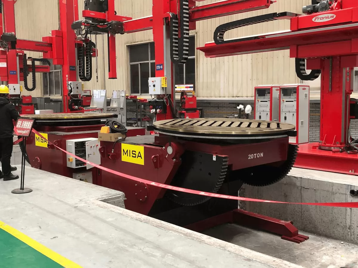
3.1 Welding Turning Table
The welding turning table — also called a welding turntable or rotary welding positioner — is the most widely used positioner type. It provides a single motorised rotation axis on a horizontal or fixed-tilt faceplate. The workpiece is bolted or clamped to the rotating table surface; the table rotates at the programmed weld travel speed while the torch or weld head remains fixed. Welding turning tables are ideal for:
- Circumferential flange-to-pipe welds, nozzle welds, and boss welds
- Small to medium pressure vessel heads and shell flanges
- Valve bodies and fitting assemblies
- Structural components requiring a single flat-position rotation pass
Welding turning tables range from bench-top models (50 kg capacity, 300 mm table diameter) for instrument valve production, up to large-capacity floor-standing models (5,000 kg, 2,000 mm table diameter) for heavy pressure vessel flange welding. Most turning tables include a fixed tilt angle (typically 0°, 45°, or 90°) set during setup, rather than motorised in-cycle tilt adjustment.
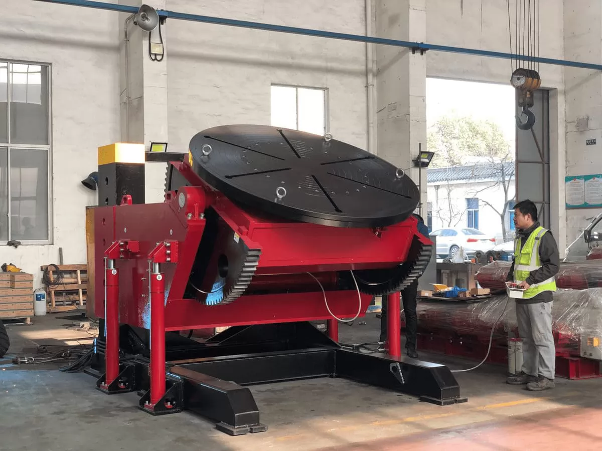
3.2 Hydraulic Positioner
The hydraulic welding positioner combines motorised rotation with hydraulic cylinder-powered tilt — enabling heavy workpieces to be tilted smoothly from 0° to 135° under full load. The hydraulic tilt system provides far greater tilt force than a motorised worm-gear drive at equivalent frame size, making hydraulic positioners the standard choice for workloads above 3–5 tonnes where motorised tilt would require prohibitively large gearboxes.
Hydraulic positioners are the workhorse of heavy pressure vessel fabrication, large valve assembly, heavy structural steel welding, and any application involving large, asymmetrically loaded workpieces. Key advantages over all-electric positioners in the heavy-duty range include: higher tilt torque at lower frame weight; smooth, controllable tilt speed independent of load; self-locking in any tilt position under hydraulic pressure; and inherent overload protection through the hydraulic relief valve system.
Capacities range from 3 tonnes up to 200+ tonnes for the largest bespoke hydraulic positioner systems. Leading suppliers include Pandjiris Inc. (USA), Key Plant Automation (Sweden/UK), and IRCO Automation (USA).
_1774416863_WNo_1280d960.webp)
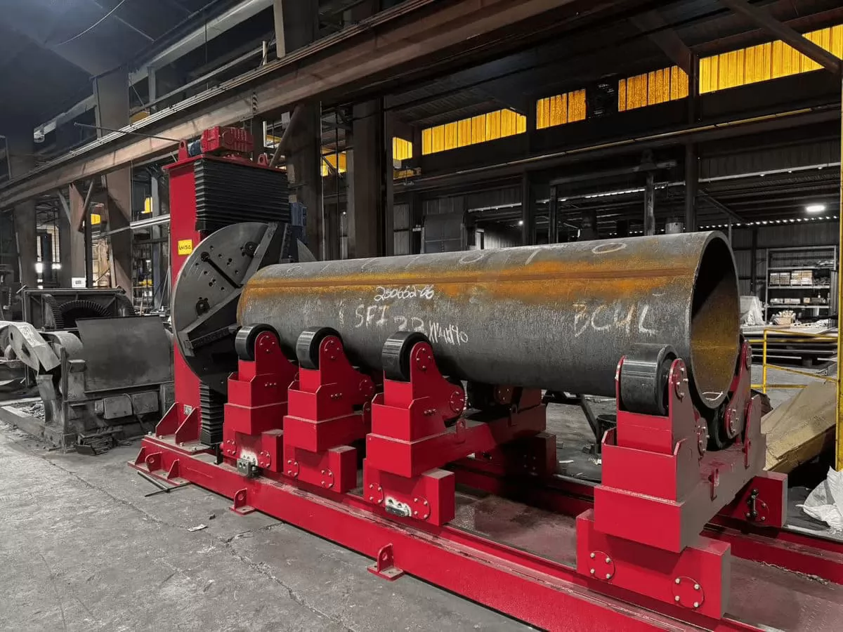
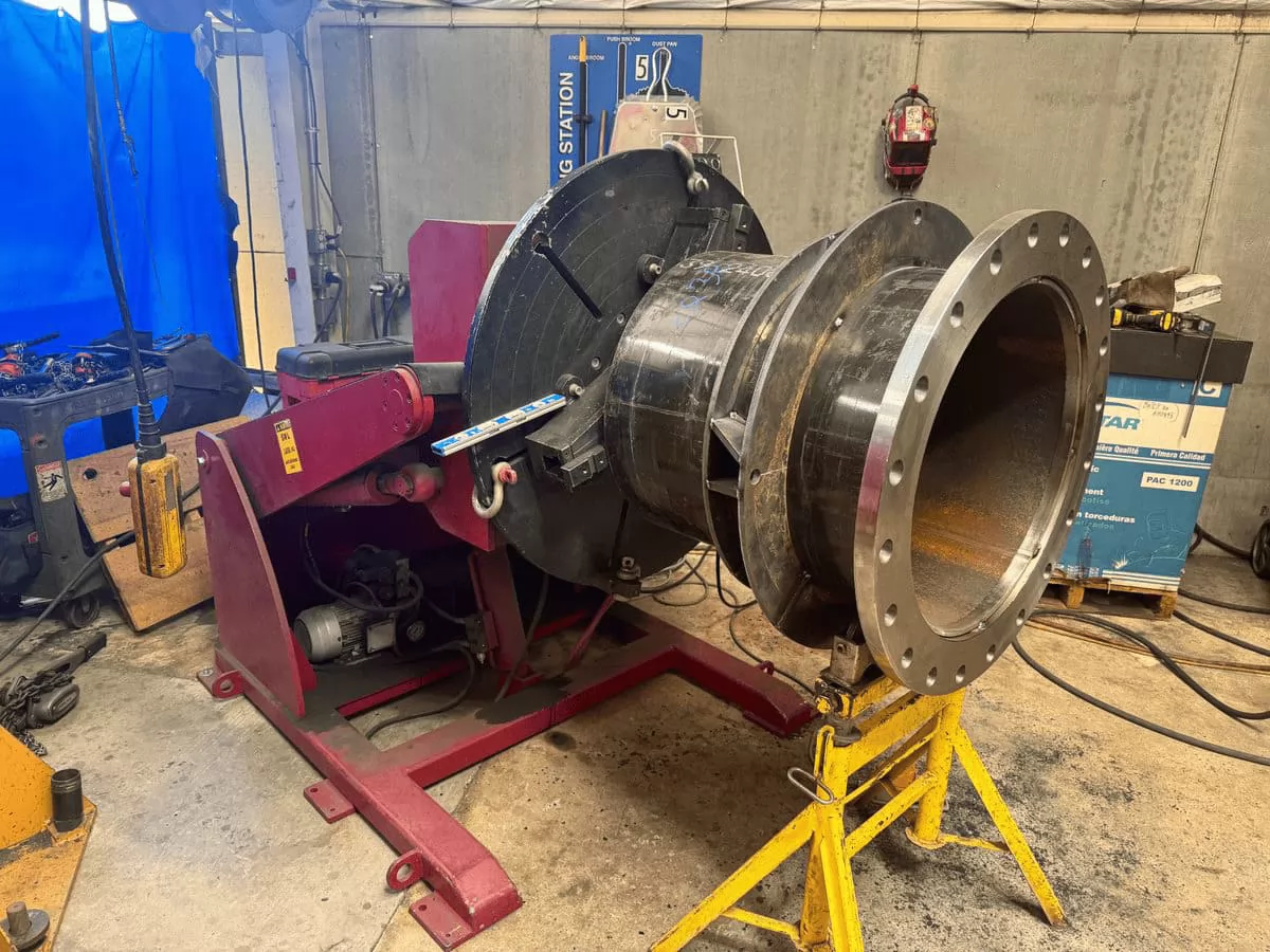
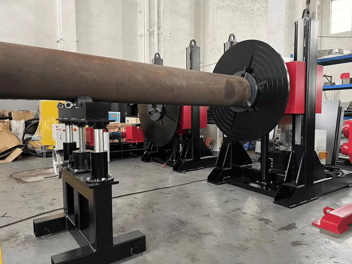
3.3 Head and Tail Stock Positioner
The head and tail stock positioner — also called a between-centres positioner or pipe spool positioner — supports the workpiece between a driven headstock (with faceplate, chuck, or gripper) and a passive or motorised tailstock. The headstock rotates the workpiece at the controlled weld speed; the tailstock provides the opposite-end support. This configuration is the standard solution for:
- Pipe spools and pipeline fittings — supported between centres, rotated for circumferential weld passes at any position along the spool length
- Pressure vessel shell courses — longer than can be supported on a single-faceplate positioner
- Shafts, axles, and cylindrical structural members — requiring rotation without the overhang stress of a cantilevered faceplate load
- Long elbow and bend assemblies — positioned between centres for flange-to-elbow and elbow-to-pipe butt welds
The key advantage over a welding rotator is that the workpiece is gripped and driven from one end — providing controlled rotation for welding without relying on friction between the workpiece OD and drive rolls. This is essential for workpieces with irregular, non-circular cross-sections, variable-diameter spools, or assemblies where OD contact rolling is impractical.


3.4 L-Type Welding Positioner
The L-type welding positioner — sometimes called an elbow positioner, cantilever positioner, or swing-arm positioner — mounts the faceplate on the end of a horizontal L-shaped arm rather than directly above the rotation base. This geometry gives the workpiece clearance below and around the faceplate, enabling it to be tilted past vertical (up to 135°) and rotated through 360° without the workpiece or fixture colliding with the base frame.
The L-type configuration is the preferred choice for any application where the workpiece must pass through or past the base level — including:
- Excavator bucket and boom arm welding — the bucket must clear the base as it rotates through all positions
- Pipe elbows and bends — asymmetric geometry requires full freedom of rotation without base contact
- Complex structural subframes and frames — multiple weld joints requiring different orientations in a single setup
- Heavy flanged assemblies — where access around the workpiece is required during welding

4. Technical Specifications by Positioner Type
| Parameter | Turning Table | Hydraulic | Head & Tail Stock | L-Type |
|---|---|---|---|---|
| Load Capacity | 50 kg – 5,000 kg | 500 kg – 200 T+ | 500 kg – 50 T | 100 kg – 20 T |
| Faceplate / Table Dia. | 300 – 2,000 mm | 500 – 3,000 mm | 250 – 1,500 mm (headstock) | 400 – 2,000 mm |
| Tilt Range | 0° – 90° (manual or fixed) | 0° – 135° (motorised hydraulic) | 0° – 90° or headstock tilt | 0° – 135° (motorised) |
| Rotation Speed | 0.05 – 5 rpm | 0.05 – 2 rpm | 0.05 – 5 rpm | 0.05 – 3 rpm |
| Tilt Drive | Manual or motorised screw | Hydraulic cylinder + pump | Manual or motorised | Motorised worm gear |
| Rotation Accuracy | ± 0.5° | ± 0.5° | ± 0.2° (servo option) | ± 0.5° |
| Hollow Through-Hole | Optional (Ø50–Ø300 mm) | Optional | Standard (through-bore) | Optional |
| Control | Foot pedal / pendant | Pendant / HMI / PLC | Pendant / PLC sync | Pendant / PLC |
| Typical Applications | Flanges, valves, small vessels | Heavy vessels, large frames | Pipe spools, long shafts | Buckets, elbows, frames |
| Welding Processes | MIG/MAG (GMAW) · TIG (GTAW) · SAW (on large units) · Plasma · Manual SMAW / FCAW | |||
| Power Supply | 415V / 3Ø / 50 Hz; 460V / 60 Hz (North America); CE / UL / CSA options available | |||
Always specify the eccentric moment — not just the total weight — when sizing a welding positioner. A workpiece weighing 500 kg but with its centre of gravity offset 600 mm from the faceplate centre generates an eccentric moment of 300 kg·m. Most manufacturers rate their positioners for a centre-of-gravity at a specified distance from the faceplate (typically 200–500 mm depending on model). Exceeding the rated eccentric moment will overload the rotation drive, tilt drive, and bearings — even if the total weight is within the capacity rating.
5. Industrial Applications

5.1 Pipe Welding & Pipeline Spool Fabrication
Pipe spool fabrication is among the highest-volume applications for welding positioners. A head and tail stock positioner with a hollow-bore headstock (allowing the pipe bore to pass through the spindle for internal TIG root pass access) is the standard configuration for ASME B31.3 and B31.1 piping fabrication. The positioner presents each circumferential butt weld joint in the flat (1G) position, enabling SAW or MIG fill and cap passes at maximum deposition rate. For small-bore pipe (< 100 mm), bench-top welding turning tables with collet chucks are the preferred solution.
5.2 Valve Body & Fitting Fabrication
Valve body welding — including gate valve, ball valve, check valve, and control valve body assembly — involves multiple weld joints on a complex, asymmetric casting or forging. An L-type or hydraulic positioner allows the heavy valve body to be tilted and rotated to present each port flange weld, body seam, or nozzle connection in the flat position without unclamping or reclamping. Applicable standards: ASME B16.34 (valves) and API 6A / API 600 (wellhead and pipeline valves).
5.3 Excavator Bucket & Ground Engaging Tool Welding
Excavator buckets, dozer blades, grader blades, and ground engaging tools are large, asymmetric, multi-joint weldments — exactly the application family for which the L-type positioner was designed. The bucket or blade is mounted on the faceplate and can be rotated and tilted through all required positions to present each fillet weld, overlay bead, tooth adapter weld, or wear plate attachment joint in the flat position. A single L-type positioner setup replaces multiple manual repositioning operations by crane — typically reducing weld cycle time by 40–60% for excavator bucket production.
5.4 Pipe Elbow & Bend Assembly Welding
Long-radius and short-radius elbows, reducing bends, and mitre-cut elbow sections require precise angular repositioning between each butt weld pass. The L-type positioner — with its full 360° rotation and 135° tilt capability — enables the elbow or bend assembly to be rotated to each weld joint position without any intermediate crane handling. Particularly critical for large-bore elbows in high-pressure pipeline service to API 1104 or ASME B31.4/B31.8 where weld procedure qualification controls are stringent.
5.5 Pressure Vessel Head & Nozzle Welding
Pressure vessel head-to-shell seams, nozzle-to-shell welds, and man-way ring welds are among the most demanding positioner applications — requiring precise tilt control to maintain the correct weld pool geometry on contoured surfaces, and smooth rotation speed control to maintain consistent weld travel speed around the nozzle OD. Hydraulic positioners are the standard choice for heads and nozzles above 3 tonnes; welding turning tables serve smaller vessels. Applicable codes: ASME Section VIII Div. 1 and EN 13445.
5.6 Structural Steel & Heavy Engineering
Welded box girders, crane saddles, offshore jacket node cans, bogie frames, and military vehicle hulls all benefit from positioner-assisted welding. For structural steel welding to AWS D1.1 or EN ISO 3834, the positioner enables prequalified flat-position joint configurations — reducing the number of qualified welding procedures required and maximising deposition efficiency.
6. Welding Positioner vs. Alternative Equipment
| Equipment | Best For | Limitation vs. Positioner |
|---|---|---|
| Welding Positioner | Any geometry workpiece; tilt & rotate; asymmetric components; in-cycle repositioning | — |
| Welding Rotator | Cylindrical workpieces on OD surface; continuous rotation; large heavy vessels and pipes | Cannot tilt; requires cylindrical OD contact; unsuitable for flanged or asymmetric parts |
| Column & Boom Manipulator | Torch/head positioning; longitudinal seam access; reach over large workpieces | Does not move the workpiece — must be combined with a positioner or rotator |
| Manual Repositioning (Crane) | Very occasional repositioning; very large components without a positioner | Slow; interrupts welding; rigging risk; no speed control; high operator fatigue |
| Welding Robot | High-mix / low-volume; complex 3D seam paths; small to medium components | Complex programming; high initial cost; limited payload for very heavy workpieces |
7. How to Select the Right Welding Positioner
Step 1 — Identify Workpiece Geometry & Weight
- Cylindrical, symmetric: Welding rotator may be sufficient; positioner adds tilt capability for nozzles and heads
- Long, shaft-like (L/D > 3): Head and tail stock positioner — eliminates cantilever overhang stress
- Asymmetric, flanged, structural: L-type or hydraulic positioner — full tilt and rotation freedom
- Heavy (> 3 T) with significant tilt requirement: Hydraulic positioner — only practical tilt solution at this weight range
Step 2 — Calculate the Eccentric Moment
- Eccentric moment (kg·m) = Workpiece weight × Distance from faceplate centre to workpiece CoG
- Confirm the positioner's rated eccentric moment exceeds your calculated value
- Include fixture plate and chuck weight in the calculation
Step 3 — Define Tilt & Rotation Requirements
- Number of weld joints and required presentation angles
- Minimum rotation speed (for low-speed TIG applications — confirm stable speed at minimum required mm/min at the joint radius)
- Whether full 360° continuous rotation or indexed positioning is required
Step 4 — Control & Integration Requirements
- Manual foot pedal + pendant (for semi-automatic and manual welding)
- PLC integration for synchronised automated welding cells
- Hollow through-hole requirement (for TIG root pass access on pipe bores)
Step 5 — Certification Requirements
- EU / UK: CE marking — Machinery Directive 2006/42/EC
- USA: UL 508A; OSHA 29 CFR 1910.212
- Canada: CSA Z432
8. Integration with Manipulators & Rotators
A welding positioner in isolation handles workpiece repositioning. Combined with a column-and-boom welding manipulator, the cell becomes a fully automated welding station capable of unattended multi-pass welding from a single setup.
8.1 Positioner + Column & Boom Manipulator
The positioner rotates the workpiece at the WPS-required weld travel speed; the manipulator's boom holds the torch stationary at the optimal position. On PLC-integrated systems, the positioner rotation speed and manipulator boom travel speed share a common master reference — ensuring consistent travel speed at the joint regardless of joint radius changes. This is the standard automated cell configuration for pressure vessel nozzle welding, flange welding, and structural component welding.
8.2 Positioner + Welding Rotator (Hybrid Cells)
For fabricators processing both cylindrical shells (on rotators) and asymmetric components (on positioners), a shared column-and-boom manipulator can serve both — repositioning between the rotator and positioner station as required. This maximises capital utilisation in multi-product fabrication shops.
9. Safety Standards & Regulatory Compliance
| Standard / Directive | Scope | Market |
|---|---|---|
| Machinery Directive 2006/42/EC | CE marking; essential health & safety requirements for machinery | EU / UK |
| IEC 60204-1 | Safety of electrical equipment of machines | Global |
| OSHA 29 CFR 1910.212 | General machine guarding; US manufacturing facilities | USA |
| CSA Z432 | Safeguarding of machinery — Canada | Canada |
| EN ISO 14731 | Welding coordination — tasks and responsibilities | EU / Global |
| EN ISO 3834 | Quality requirements for fusion welding | EU / Global |
| ASME BPVC Section IX | Welding procedure qualification — vessel and piping applications | USA / Global |
10. Frequently Asked Questions
What is the difference between a welding positioner and a welding rotator?
A welding positioner grips the workpiece on a faceplate or between centres and can both rotate and tilt it — making it suitable for asymmetric, flanged, or complex-geometry components including valves, elbows, excavator buckets, and vessel heads. A welding rotator supports a cylindrical workpiece from below on turning rolls, rotating it about its own axis — suitable for continuous circumferential welding of pipes, vessels, and tanks. The key distinction: a positioner can handle any workpiece geometry; a rotator is limited to workpieces with a consistent cylindrical OD. In many automated welding cells, both are present — the rotator handles large cylindrical shell courses while the positioner handles nozzle and head welds.
Which positioner type is best for excavator bucket welding?
The L-type welding positioner is the industry standard for excavator bucket and ground-engaging tool welding. The L-type configuration provides full 360° rotation and 0°–135° motorised tilt — allowing the bucket to be rotated through all positions without the body or lip contacting the base frame. The faceplate is typically fitted with a custom fixture plate matching the bucket attachment boss bolt pattern. The L-type positioner replaces multiple crane repositioning operations per bucket, typically reducing bucket assembly weld cycle time by 40–60%. For very heavy buckets (above 5 tonnes), a hydraulic L-type or hydraulic positioner with custom fixture is required to provide adequate tilt force.
What is eccentric moment and why does it matter for positioner selection?
Eccentric moment (or offset moment) is the bending moment applied to the positioner's rotation and tilt bearings by a workpiece whose centre of gravity is offset from the faceplate centre. It is calculated as: Eccentric Moment (kg·m) = Workpiece weight (kg) × CoG offset from faceplate centre (m). A 1,000 kg valve body with its CoG 400 mm from the faceplate centre imposes an eccentric moment of 400 kg·m — which may exceed the rated moment of a positioner with a 1,000 kg weight capacity but a 300 kg·m moment rating. Exceeding the rated eccentric moment overloads the rotation drive gearbox, tilt cylinder or screw, and the main turntable bearing — leading to accelerated wear and potential structural failure. Always calculate eccentric moment and compare it against the positioner's rated value before purchasing.
Can a welding positioner be used for TIG welding of stainless steel pipe?
Yes — welding positioners are widely used for TIG (GTAW) welding of stainless steel, duplex stainless, and high-alloy pipe and fittings. For stainless steel pipe spool fabrication, a head and tail stock positioner with hollow-bore headstock is the preferred configuration: the hollow bore (typically 50–300 mm ID) allows the purge gas supply tube to pass through the spindle centre into the pipe bore for back-purging during the TIG root pass — a mandatory requirement for hygienic-grade, process-grade, and corrosion-resistant piping fabrication. The rotation drive must be capable of stable, smooth speed control at very low rotation speeds (down to 0.03–0.05 rpm) for slow TIG travel speeds — specify closed-loop encoder feedback if TIG welding is the primary application.
How is a hydraulic positioner different from an electric positioner?
Both hydraulic and electric positioners provide motorised tilt and rotation — but their tilt drive systems differ fundamentally. An electric positioner uses a motor-driven worm gearbox or screw jack for tilt — suitable for loads up to approximately 3–5 tonnes before the gearbox becomes prohibitively large and expensive. A hydraulic positioner uses a hydraulic cylinder for tilt — providing far greater tilt force at equivalent frame size, smooth and continuously controllable tilt speed, inherent self-locking in any tilt position under hydraulic pressure, and overload protection through the hydraulic relief valve. Hydraulic positioners are the standard choice for capacities above 3–5 tonnes. The hydraulic power unit requires periodic oil changes and filter maintenance; electric positioners are simpler to maintain for light-duty applications.
What is a hollow-bore welding positioner and when do I need one?
A hollow-bore welding positioner (also called a through-hole or hollow-spindle positioner) has a hollow shaft through the headstock centre — allowing pipes, purge gas tubes, wiring harnesses, or mandrels to pass through the spindle and through the rotating workpiece. The primary applications are: (1) pipe TIG root pass welding, where the bore must be continuously back-purged with argon to prevent oxidation of the root weld bead on stainless steel or reactive alloy pipe; (2) weld overlay cladding of pipe bores, where the cladding torch must be inserted through the centre; and (3) electrical or fluid connections to a rotating workpiece or fixture. Hollow-bore diameters range from 50 mm (bench-top pipe spool positioners) to 300 mm (large pipeline spool headstocks). If your application involves stainless, duplex, or alloy piping with a TIG root pass requirement, specify a hollow-bore headstock as standard.
What capacity welding positioner do I need for pressure vessel nozzle welding?
The required positioner capacity for pressure vessel nozzle welding depends on the vessel head or shell section weight plus any fixture, plus the eccentric moment generated by the offset between the vessel's CoG and the faceplate centre. As a general guideline: vessels up to 500 kg and nozzle OD up to 200 mm are typically handled by a 500 kg – 1 T welding turning table; vessels up to 3,000 kg use a 3–5 T motorised hydraulic positioner; vessels above 3,000 kg require a heavy hydraulic positioner or a specialised positioner system. Always calculate the eccentric moment rather than relying on weight alone — a large-diameter vessel with a long nozzle offset may require a positioner rated significantly above the vessel weight to accommodate the bending moment. Confirm with ASME Section VIII or EN 13445 weld procedure requirements when specifying automated nozzle welding cells.
Can a welding positioner be synchronised with a welding manipulator or robot?
Yes — positioner synchronisation with a column-and-boom welding manipulator, side-beam welding carriage, or articulated welding robot is standard practice in all modern automated welding cells. On PLC-integrated systems, the positioner's rotation speed is locked to the welding manipulator's torch travel speed through a shared master speed reference — ensuring constant weld travel speed at the joint radius. For robot integration, the positioner is typically configured as an external positioner axis within the robot's motion control system (using Fanuc, KUKA, ABB, or Panasonic robot controller I/O), enabling coordinated multi-axis motion for complex weld path following. Confirm the positioner's control interface (EtherNet/IP, Profinet, DeviceNet, or analogue 0–10V) matches your robot or PLC platform before purchasing.
What is the difference between an L-type positioner and a standard tilting positioner?
A standard tilting positioner mounts the faceplate directly above the base frame — when the table tilts past 90°, the workpiece or fixture will contact the base frame, limiting the effective tilt range to approximately 90–100°. An L-type positioner offsets the faceplate on a horizontal arm extending from the tilt pivot — raising the workpiece above the base level and providing clearance for the workpiece to tilt through the full 0°–135° range and rotate 360° without base contact. This clearance is essential for excavator buckets, elbows, curved structural subframes, and any workpiece that extends below the faceplate mounting surface at certain tilt angles. The trade-off is that the L-arm introduces a larger eccentric moment at the tilt pivot for a given workpiece weight — L-type positioners are therefore rated at lower total weight capacities than equivalent-frame standard positioners.
How do I prevent welding current from damaging the positioner bearings?
Welding current returning through the positioner frame and main turntable bearing is one of the most common causes of premature bearing failure on welding positioners — the arc current causes pitting and fluting of the bearing raceways (electrical erosion damage) within weeks of operation. The correct practice, as required by all major positioner manufacturers and by Pandjiris Inc.'s published safety bulletins, is to always connect the welding earth (ground) return clamp directly to the workpiece — never relying on the positioner frame as the current return path. On positioners fitted with slip-ring current collectors (a standard option on most manufacturers' turning table and head-stock models), the slip ring provides a low-resistance earth return path through the positioner without current flowing through the bearings — specify a slip-ring earth collector as standard on all positioners used for MIG, TIG, or SAW welding.
What maintenance does a welding positioner require?
Welding positioners are mechanically robust and require moderate but consistent maintenance to deliver reliable long-term service:
- Daily: Check for unusual noise or vibration; verify earth return clamp is connected directly to the workpiece; clean weld spatter from faceplate and T-slots; check hydraulic fluid level (on hydraulic positioners).
- Weekly: Inspect gearbox oil level; check all fastener torques on faceplate and fixture bolts; verify tilt lock (if manual) is fully engaged before loading workpiece; inspect hydraulic cylinder seals for leaks (hydraulic positioners).
- Monthly: Lubricate rotation ring gear and pinion drive; check slip-ring contact condition and carbon brush wear (if fitted); verify rotation speed accuracy against a reference tachometer; inspect frame welds for fatigue cracking at high-stress joints.
- Annually: Full gearbox oil change; hydraulic oil and filter change (hydraulic positioners); main turntable bearing inspection; calibration of speed control; electrical insulation testing of the earth isolation system.
Are CE-certified welding positioners required for the European market?
Yes. Any welding positioner placed on the EU, EEA, or UK market must bear CE marking (UK: UKCA marking post-Brexit) in compliance with the Machinery Directive 2006/42/EC. CE certification requires: a risk assessment to EN ISO 12100; compliance with applicable harmonised standards including IEC 60204-1 (electrical safety) and EN ISO 13849-1 (safety-related control systems); a Technical File; and a signed Declaration of Conformity. Equipment imported from outside the EU (including China, USA, or other markets) must still carry valid CE marking issued by the manufacturer or EU authorised representative — the EU importer bears legal responsibility if CE-marking documentation is absent or incorrect. Always request copies of the Declaration of Conformity, risk assessment summary, and Technical File index before accepting delivery of any CE-marked welding positioner.
What is the typical lead time for a welding positioner?
Standard welding turning tables and L-type positioners in catalogue capacities (up to 3–5 tonnes) typically carry lead times of 2–6 weeks from stock or semi-stock configurations. Hydraulic positioners in the 5–50 tonne range are typically 6–12 weeks as they involve custom hydraulic circuit design and frame fabrication. Head and tail stock systems with custom chuck bore, adjustable tailstock span, and PLC-synchronised output are typically 8–14 weeks. Very large bespoke systems — hydraulic positioners above 50 tonnes, multi-axis coordinated positioner cells, or special-purpose excavator bucket or wind tower flange welding configurations — require 12–24 weeks depending on engineering content. Always confirm lead time against your production start date at purchase order stage and build commissioning and operator training time into your project schedule.
11. Industry References & Further Reading
- American Welding Society (AWS) — D1.1 Structural Welding Code & Standards Library
- International Institute of Welding (IIW) — Best-Practice Welding Guidelines
- The Welding Institute (TWI) — Welding Automation Technology Research
- ASME BPVC Section VIII — Pressure Vessel Code
- ASME B31.3 — Process Piping Code
- API 1104 — Welding of Pipelines and Related Facilities
- API 6A / API 600 — Wellhead & Pipeline Valve Standards
- Pandjiris Inc. — Welding Positioners Product Documentation (USA)
- Key Plant Automation — Welding Positioners Range (Sweden/UK)
- IRCO Automation — Welding Positioners & Manipulators (USA)
- Lincoln Electric — Welding Automation & Process Reference
- ISO — EN ISO 3834: Quality Requirements for Fusion Welding
- European Commission — Machinery Directive 2006/42/EC
Welding Positioners — In the Field
Ready to Upgrade Your Welding Productivity?
Talk to our engineering team about your welding positioner requirements — turning table, hydraulic, head & tail stock, or L-type. Standard and fully bespoke configurations available. No-obligation technical consultation and quotation.