


.png)


In today's competitive fabrication landscape, consistency, repeatability, and throughput define the difference between a profitable workshop and one that struggles to meet delivery schedules. A welding manipulator column and boom is among the most productive investments a fabricator can make — enabling precise torch positioning over large or complex workpieces while dramatically reducing operator fatigue and rework rates.
Whether you are fabricating pressure vessels to ASME Section VIII requirements, welding wind tower sections up to 30 metres in length, or running high-deposition submerged arc weld (SAW) passes on large pipe spools, a column-and-boom manipulator is the industry-standard solution for torch positioning in automated and semi-automated welding cells.
This guide has been written for engineers, procurement managers, and welding coordinators — drawing on the practices and product philosophies of leading global suppliers such as Keyplant (Sweden), Red-D-Arc (North America), LJ Welding Automation (Canada), IRCO Automation (USA), and Redrock Automation.
Related Search Terms
1. What Is a Welding Manipulator Column and Boom?
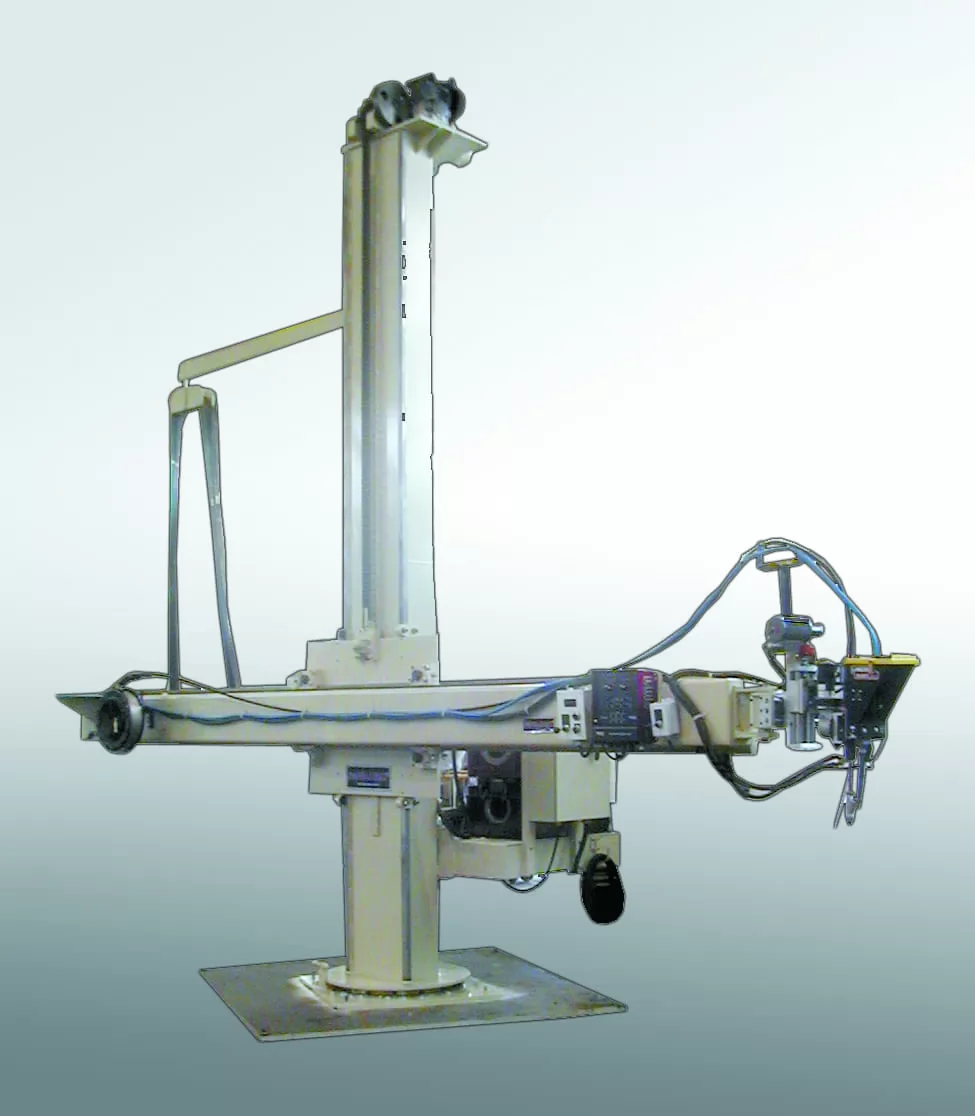
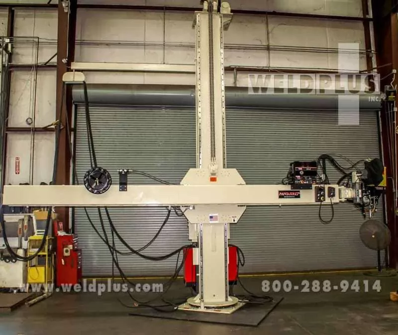
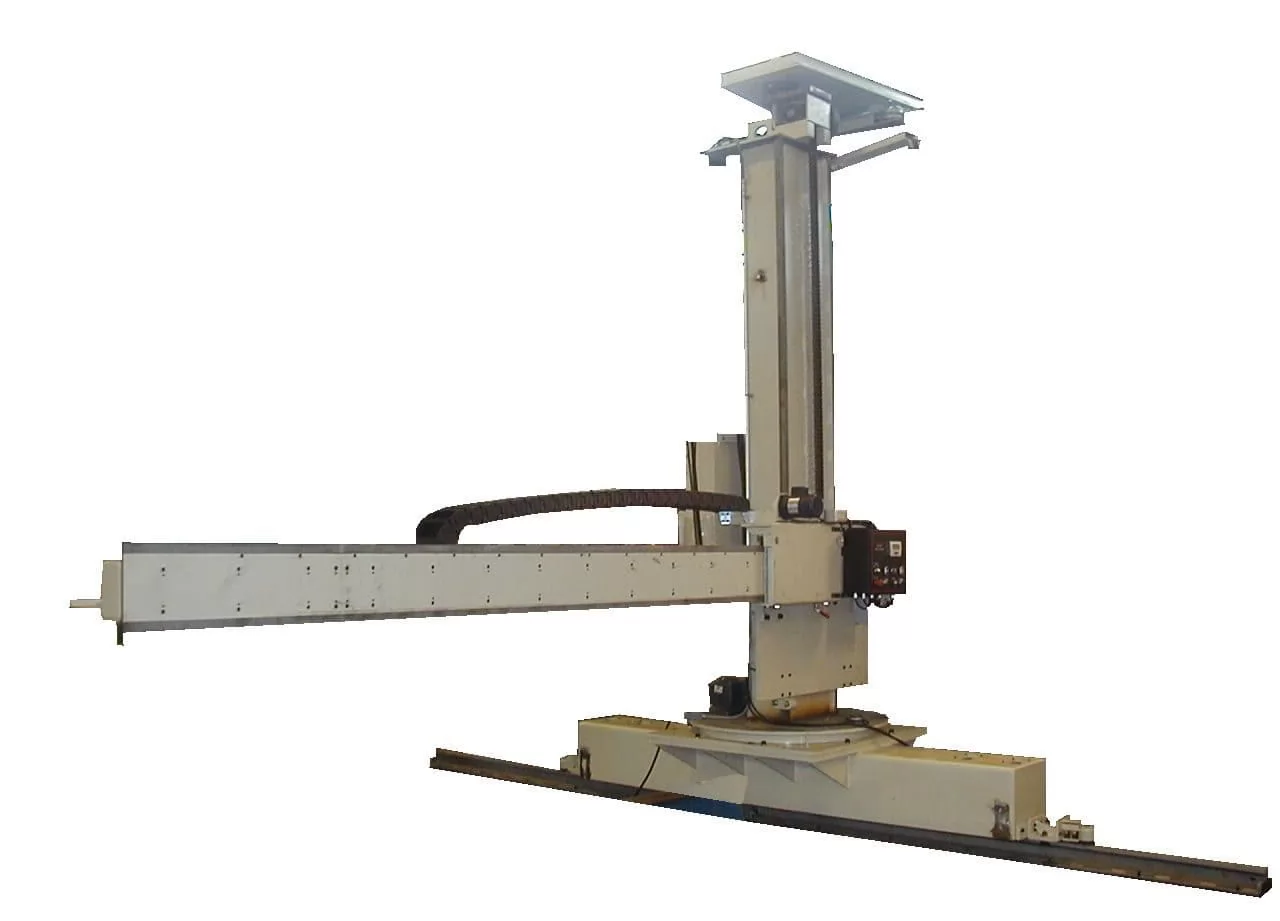
A welding manipulator column and boom — sometimes referred to as a column-and-boom welding system, boom welding manipulator, or welding column boom — is a mechanised torch positioning system consisting of a vertical column (mast) and a horizontal boom arm. The combination provides two-axis (XY) positioning of the welding torch or weld head over a stationary or slowly rotating workpiece.
The vertical column carries a motorised carriage that travels up and down under inverter-controlled drive. Mounted to this carriage is the horizontal boom, which extends inward or outward to place the torch at any point within the working envelope. A cross-slide or torch manipulation head at the boom tip provides fine adjustment of arc gap and travel angle.
Core Components at a Glance
- Column (Mast): Fabricated from heavy structural steel, stress-relieved and precision-machined; provides vertical travel. Floor- or track-mounted.
- Vertical Carriage: Rides on precision-ground linear guides or rack-and-pinion drives; supports the boom assembly.
- Boom Arm: Extends horizontally from the carriage; must be sized to reach beyond the maximum workpiece radius with capacity to spare.
- Boom Carriage: Drives the horizontal in/out travel of the boom relative to the column.
- Torch / Weld Head Mounting: Accepts MIG, TIG, SAW, plasma, or overlay weld heads; cross-slide and tilt adjustment standard on most models.
- Drive System: AC inverter drives (Siemens, Danfoss, or Allen-Bradley) providing stepless, repeatable speed control.
- Control System: PLC-based with pendant, remote joystick, HMI touch-screen, or full CNC interface options.
The term welding manipulator can refer to any device that positions a welding torch. In industrial welding, column and boom manipulator specifically denotes a floor-standing, two-axis (XY) system — as distinct from a bench-top torch manipulator or a robot arm.
2. How Does a Column and Boom Welding Manipulator Work?
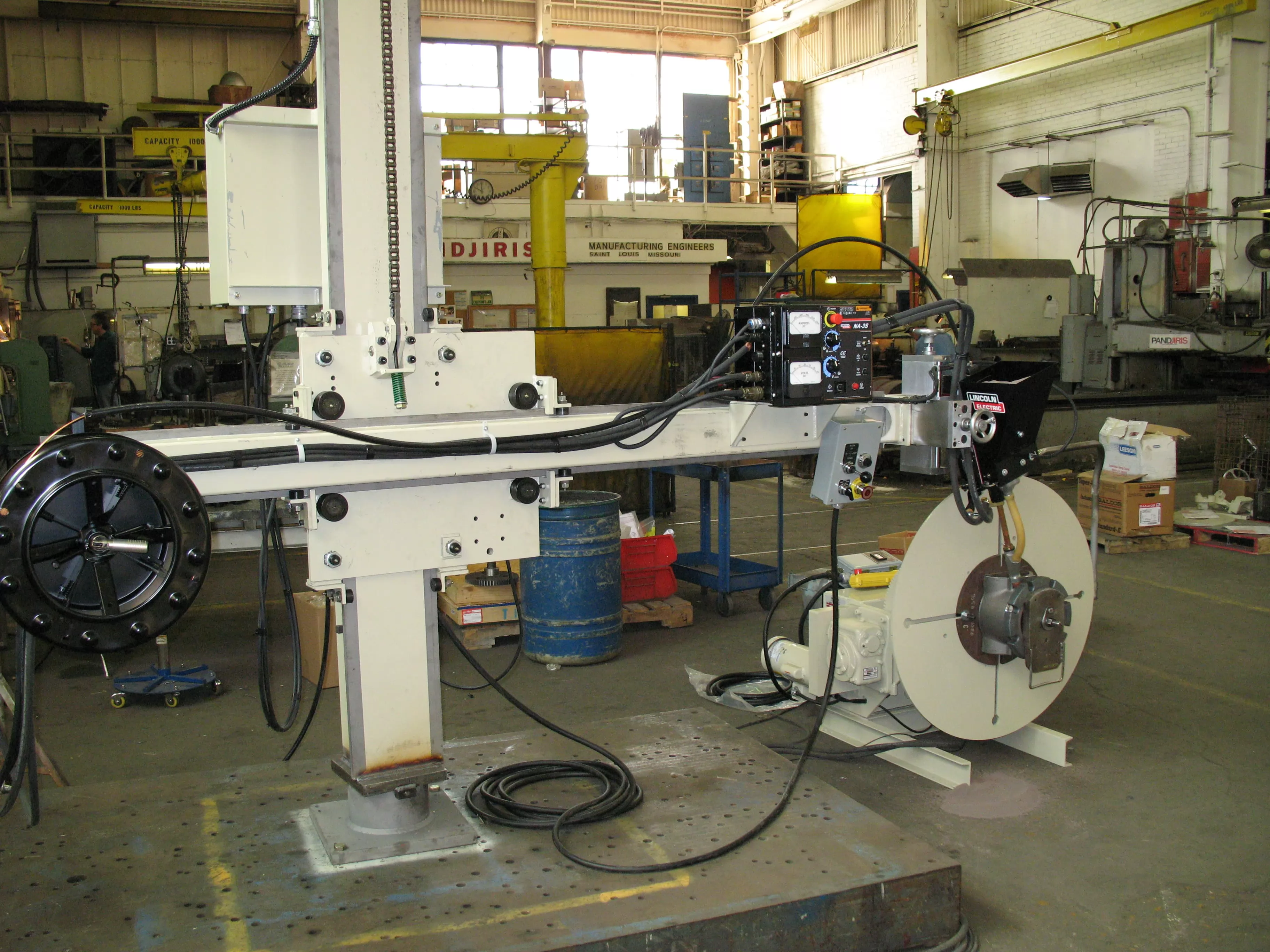
The operating principle is elegant in its simplicity. The column-and-boom manipulator is positioned alongside the workpiece — typically used in tandem with a welding rotator or welding positioner that rotates or tilts the component. The manipulator's boom is extended to place the welding torch directly over the weld joint, and the torch remains in a fixed, optimised position while the workpiece rotates beneath it.
This approach converts what would otherwise be an all-position weld into a flat-position weld — a technique strongly endorsed by the American Welding Society (AWS) and the International Institute of Welding (IIW) for improving deposition rates, bead geometry, and metallurgical properties.
Circumferential seam welding of a pressure vessel shell course using a column-and-boom manipulator paired with a welding rotator can achieve SAW deposition rates of 15–25 kg/hr per wire — compared to 3–5 kg/hr using manual SMAW. This difference directly impacts delivery schedules and fabrication cost-per-metre.
Synchronised Motion Control
On modern systems, the rotator's turning speed and the manipulator's boom travel speed are synchronised through a shared PLC or coordinated motion controller. This ensures that the weld travel speed at the joint surface remains constant regardless of workpiece diameter — a critical requirement for maintaining the correct heat input as specified in the ASME Boiler and Pressure Vessel Code, Section IX qualified welding procedure specifications (WPS).
3. Types of Column and Boom Welding Manipulators
Suppliers such as Keyplant, LJ Welding, and IRCO Automation categorise their column-and-boom product lines into several main configurations. Understanding these types is the first step in specifying the correct system.
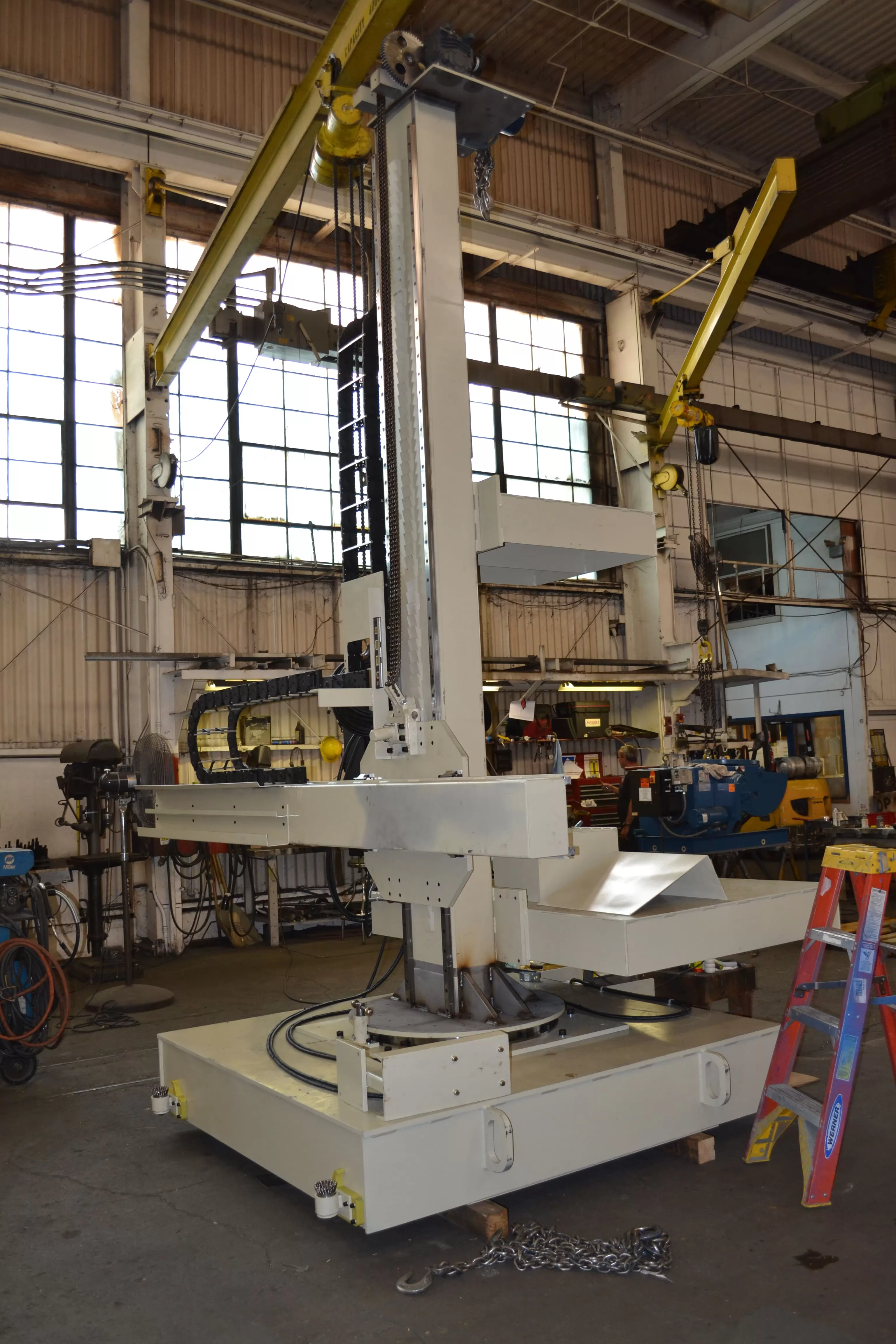
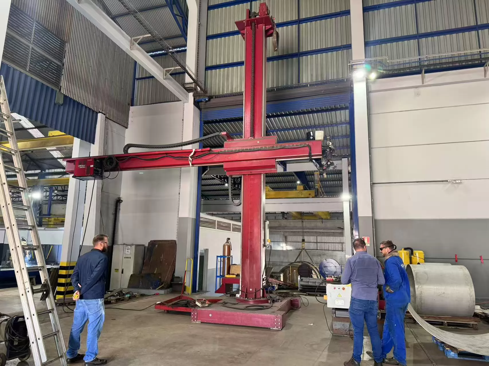
3.1 Fixed (Floor-Mounted) Column Manipulator
The most cost-effective and rigid configuration. The column base is bolted directly to a reinforced concrete floor pad. Workpieces are brought to the machine. Ideal for dedicated welding bays processing similar-sized components — pressure vessel heads, flange assemblies, or pipe spools in a fixed work station. The fixed column offers the highest structural rigidity, making it the preferred choice for heavy SAW applications where boom deflection must be minimised.
3.2 Travelling Column Manipulator (Rail-Mounted)
The column is mounted on a floor-level rail track, allowing longitudinal travel along the length of the workpiece. This is the standard configuration for longitudinal seam welding of wind tower sections, storage tank shell courses, and structural beams exceeding 3 metres in length. Travel speeds along the track are typically 10–3,000 mm/min, synchronised with a seam-tracking system or simply programmed for the required weld travel speed.
Redrock Automation and LJ Welding both offer extended-travel trackway systems with column travel lengths up to 50 metres for wind tower production lines.
3.3 Telescopic Mast Manipulator
In this compact variant, the boom is housed within a telescoping mast — reducing the floor footprint significantly when the boom is retracted. Popular in offshore fabrication yards, shipbuilding facilities, and workshops where available headroom or floor space is limited. Vertical travel is achieved by extending or retracting the inner mast sections.
3.4 Cross-Carriage (XY + Cross-Slide) Manipulator
The most flexible standard configuration. In addition to vertical column travel and horizontal boom travel, a lateral cross-slide on the boom tip provides a third axis of torch positioning — effectively a Z-axis traverse. This allows the operator to fine-position the torch across the weld joint without repositioning the column, and is indispensable for multi-pass fillet welds, offset joint geometries, and twin-wire SAW applications.
For SAW circumferential welding on vessels with varying shell course diameters, always specify a cross-slide with at least ±150 mm lateral travel. This accommodates diameter changes between shell courses without repositioning the entire column.
4. Technical Specifications
The following table presents representative specification ranges for industrial column and boom welding manipulators. Actual values depend on the manufacturer and custom configuration.
| Parameter | Standard Range | Heavy-Duty Range | Notes |
|---|---|---|---|
| Column Height (Total) | 2 m – 6 m | 6 m – 14 m | Taller columns for wind towers & large vessels |
| Boom Reach | 1 m – 4 m | 4 m – 10 m | Must exceed max workpiece radius |
| Vertical Travel Speed | 10 – 1,000 mm/min | 10 – 2,000 mm/min | Variable via inverter; slow end critical for TIG |
| Horizontal Travel Speed | 10 – 1,500 mm/min | 10 – 3,000 mm/min | Matched to weld travel speed requirements |
| Boom Load Capacity | 50 – 150 kg | 150 – 500 kg | Includes torch, wire feeder, flux hopper, cables |
| Welding Processes | SAW · MIG/MAG (GMAW) · TIG (GTAW) · Plasma (PAW) · Cladding | Multi-process heads available | |
| Travel Accuracy (Repeatability) | ± 0.5 mm | ± 0.1 mm | Servo-driven systems achieve tighter tolerance |
| Column Travel (Rail) | Up to 12 m | Up to 60 m+ | For longitudinal seam welding production lines |
| Power Supply | 415V / 3-phase / 50 Hz standard; 460V / 60 Hz (North America) | CE / UL / CSA certification options | |
| Control Interface | Pendant · Remote Joystick · Touch-screen HMI · CNC / PLC | Siemens S7, AB ControlLogix common | |
For SAW applications specifically, boom load capacity is the single most critical specification. A typical single-wire SAW weld head, wire drive unit, flux hopper (15 kg loaded), and cable harness can weigh 80–120 kg at the boom tip. At full extension, this load creates significant bending moment on the boom structure — always request a detailed deflection calculation from the supplier. Both Keyplant and IRCO Automation publish boom deflection curves as standard in their product documentation.
5. Industrial Applications of Welding Manipulator Column and Boom Systems
The versatility of the column and boom welding manipulator makes it suitable across virtually every sector of heavy manufacturing. Below are the primary application areas, along with the relevant industry standards and typical welding processes.
5.1 Pressure Vessel & Heat Exchanger Fabrication
The highest-volume application for column-and-boom manipulators worldwide. Circumferential seam welding and longitudinal seam welding of pressure vessel shell courses, heads, and nozzle connections using SAW or MIG. Governed by ASME VIII (USA/Canada), EN 13445 (Europe), and EN ISO 14731 welding coordination requirements.
5.2 Wind Tower Manufacturing
Among the most demanding applications: welding longitudinal seams on conical or cylindrical tower sections up to 30 m long and 6 m in diameter. Requires travelling-column systems with extended trackways, high-duty-cycle SAW weld heads, and precise seam-tracking. A single tower section may require 200+ metres of continuous weld — fully automated column-and-boom production lines are essential for viability. Reference: DNV-ST-0126 (Support Structures for Wind Turbines).
5.3 Pipeline & Pipe Spool Fabrication
Automated butt welding of pipe spools and mainline pipe sections using column-and-boom manipulators paired with self-aligning or conventional welding rotators. Typical processes: SAW for root and fill passes on thick-wall pipe; TIG hot-pass for X65/X70 grade CRA-clad or duplex stainless steel pipe. Applicable codes include API 1104 and ASME B31.3.
5.4 Storage Tank Construction
Shell course seam welding for above-ground storage tanks per API 650 (USA) and EN 14015 (Europe). Large-diameter tanks (up to 100 m+) require travelling-column systems on extended trackways running the full circumference of the tank erection area.
5.5 Structural Steel & Heavy Engineering
Fillet and butt welding of welded I-beams, box girders, bridge components, crane girders, and offshore structural members. Typically MIG/MAG or SAW with multi-wire configurations to maximise deposition. Governed by AWS D1.1 (USA) or EN ISO 3834 quality requirements for fusion welding.
5.6 Shipbuilding & Offshore
Block assembly welding, hull panel line welding, jacket structure fabrication, and spool piece welding for floating production units (FPSOs). Governed by classification society rules: DNV, Lloyd's Register, Bureau Veritas, and ABS.
5.7 Railway & Defence
Bogie frame welding, armour plate assembly, military vehicle hull welding, and large rail infrastructure component fabrication — often requiring high-integrity MIG or TIG welding with full NDE traceability.
6. Column and Boom Manipulator vs. Alternative Equipment
Selecting the right welding automation solution requires understanding where a column-and-boom manipulator excels and where alternative equipment may be more appropriate.
| Equipment Type | Ideal Application | Limitation vs. Column & Boom |
|---|---|---|
| Column & Boom Manipulator | Large/long workpieces; high reach; SAW; automated seam welding | — |
| Welding Positioner | Small–medium asymmetric components; tilt & rotate positioning | Limited reach; unsuitable for very long workpieces |
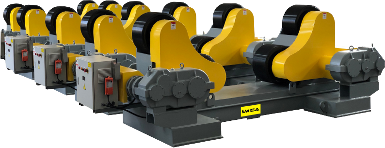
| Welding Rotator | Cylindrical pipes & vessels; continuous rotation; all diameters | No torch positioning — must be combined with a manipulator |
| Articulated Welding Robot | Complex 3D geometries; short weld seams; high mix / low volume | Payload limited for SAW; high programming cost; complex cell integration |
| Manual Welding Tractor | Simple single-pass fillet welds; site & field applications | No torch positioning; limited process control; operator dependent |
As Lincoln Electric's SAW reference guide notes, for high-deposition seam welding applications with payloads exceeding 50 kg at the torch, the column-and-boom manipulator remains the preferred solution — articulated robots being impractical at such payload levels and articulation spans.
7. How to Select the Right Welding Manipulator Column and Boom
Use the following structured checklist when specifying your system. These criteria reflect the evaluation process used by major EPC contractors and fabricators in Europe, North America, and the Asia-Pacific region.
Step 1 — Define Your Workpiece Envelope
- Maximum workpiece diameter (drives minimum boom reach)
- Maximum workpiece height (drives minimum column travel height)
- Maximum workpiece length (determines whether a travelling column is required)
- Maximum workpiece weight (for rotator and positioner sizing — not directly for manipulator)
Step 2 — Specify Your Welding Process
- SAW (Submerged Arc): Boom load capacity typically 100–300 kg; flux recovery system integration; high duty cycle drives
- MIG/MAG (GMAW): Boom load 50–100 kg; wire feeder mounting; gas hose routing
- TIG (GTAW): Boom load 30–80 kg; precise low-speed control (as low as 5 mm/min)
- Plasma / Laser Overlay: Specialised torch cooling, gas supply routing, and motion accuracy requirements
Step 3 — Determine Travel Speed Requirements
- SAW: typically 150–600 mm/min weld travel speed
- MIG/MAG: typically 200–900 mm/min
- TIG: typically 50–300 mm/min
- Confirm the drive system achieves stable speed at the lower end of the range — stepless inverter control is essential
Step 4 — Integration Requirements
- Synchronisation with rotator or positioner — confirm compatible PLC I/O protocols (e.g., Profibus, EtherNet/IP, Profinet)
- Arc length control (AVC) or seam tracking integration
- Wire feeder and welding power source interface
- Flux delivery and recovery system (SAW)
Step 5 — Certification & Market Requirements
- EU / UK: CE marking per Machinery Directive 2006/42/EC; Low Voltage Directive; EMC Directive
- USA: UL 508A panel certification; OSHA compliance per 29 CFR 1910.212
- Canada: CSA Z432 machinery safeguarding; electrical panel to CSA C22.2
- All markets: IEC 60204-1 (Safety of electrical equipment of machines)
Always request a formal boom deflection analysis at full extension under maximum payload — specified in millimetres at the boom tip. Industry best practice (as observed in Keyplant and IRCO Automation product documentation) is to limit boom tip deflection to less than L/500 (where L = boom length in mm). Excessive deflection causes arc length variation that directly affects weld bead geometry and may invalidate your WPS.
8. Integration with Welding Rotators & Positioners
A welding manipulator column and boom reaches its full potential when integrated into a complete automated welding cell. The two most common integration configurations are:
8.1 Column & Boom + Welding Rotator
The most common automated cell configuration for cylindrical components (vessels, drums, pipes). The welding rotator rotates the workpiece at a controlled, adjustable speed; the manipulator holds the torch stationary at the 12 o'clock (or 1–2 o'clock) optimal welding position. The rotator speed is synchronised to deliver the correct weld travel speed at the joint surface regardless of workpiece diameter.
Our range of conventional welding rotators and self-aligning welding rotators are fully compatible with our column-and-boom systems, including synchronised motion control through a shared master PLC.
8.2 Column & Boom + Welding Positioner
For asymmetric or non-cylindrical components — flanged assemblies, valve bodies, nozzle connections — a welding positioner tilts and rotates the workpiece to present the weld joint in the flat or horizontal-fixed position, while the boom delivers the torch to the joint. Our head-and-tailstock positioners and turntable positioners are designed for seamless integration with our manipulator range.
9. Safety Standards & Regulatory Compliance
All column-and-boom welding manipulators intended for industrial use must comply with applicable machinery safety and electrical standards. The following are mandatory or strongly recommended for equipment supplied to EU, North American, and international markets:
| Standard / Directive | Scope | Market |
|---|---|---|
| Machinery Directive 2006/42/EC | CE marking; essential health & safety requirements for machinery | EU / UK |
| IEC 60204-1 | Safety of electrical equipment of machines; wiring, e-stops, drive systems | Global |
| ISO 10218-1 / -2 | Safety requirements for industrial robots & automated welding cells | Global |
| OSHA 29 CFR 1910.212 | General machine guarding; risk reduction in US manufacturing facilities | USA |
| CSA Z432 | Safeguarding of machinery; Canadian mandatory standard | Canada |
| EN ISO 14731 | Welding coordination — tasks and responsibilities | EU / Global |
| EN ISO 3834 | Quality requirements for fusion welding — quality management system | EU / Global |
10. Frequently Asked Questions
What is the difference between a welding manipulator column and boom and a welding positioner?
A welding manipulator column and boom positions the torch or weld head — it moves the welding equipment to the joint. A welding positioner positions the workpiece — it rotates and/or tilts the component to present the weld joint in the optimum orientation. In most automated welding cells, both are used together: the positioner or rotator moves the workpiece while the manipulator keeps the torch precisely at the joint.
What welding processes are compatible with a column and boom welding manipulator?
Column-and-boom manipulators are process-agnostic. They are routinely configured for Submerged Arc Welding (SAW), MIG/MAG (GMAW), TIG (GTAW), Plasma (PAW), narrow-groove TIG, cold-wire TIG overlay, and laser-hybrid welding. The key constraint is the boom load capacity — SAW configurations with twin-wire weld heads and flux hoppers may require 150–300 kg boom capacity, while TIG setups typically require only 30–60 kg.
How do I calculate the required boom reach for my application?
The minimum boom reach equals the maximum workpiece radius + 300–500 mm clearance. For a vessel shell with a maximum outside diameter of 3,000 mm, the minimum boom reach is 1,500 + 400 = 1,900 mm. Always specify headroom for the torch assembly, cross-slide travel, and any seam-tracking sensor offset. When in doubt, size up — a longer boom on a stiffer structure is preferable to a boom at the very limit of its reach.
Can the column and boom manipulator be synchronised with a welding rotator?
Yes — this is standard practice in all modern automated welding cells. The rotator's peripheral speed (mm/min at the workpiece surface) is matched to the WPS-required weld travel speed. On PLC-controlled systems, a master/slave relationship ensures that if the rotator speed is adjusted, the manipulator's boom travel speed is proportionally corrected. Refer to the AWS D1.1 code requirements for weld procedure qualification to understand why maintaining consistent travel speed is critical.
What is the typical lead time for a column and boom welding manipulator?
Standard configurations with commonly stocked column heights (2–4 m) and boom lengths (2–4 m) typically carry lead times of 4–8 weeks. Heavy-duty or bespoke systems — large column heights, extended boom reaches, special SAW configurations, or travelling-column systems with custom trackways — typically require 10–20 weeks from order placement. Always confirm lead time in your purchase order, as delays in welding automation equipment frequently impact production start dates for major fabrication projects.
Are your column and boom manipulators CE certified for the European market?
Yes. Our welding manipulator column and boom systems are CE marked in accordance with Machinery Directive 2006/42/EC, with supporting documentation including technical file, Declaration of Conformity, risk assessment, and operating manuals. UL/CSA-certified variants for the United States and Canadian markets are available upon request.
What is the difference between a fixed column and a travelling column manipulator?
A fixed column is bolted permanently to the floor — the workpiece is brought to the machine. It offers maximum structural rigidity and is the most cost-effective solution for short or medium-length components. A travelling column is mounted on a floor-level rail track, allowing the manipulator to travel longitudinally along the length of the workpiece. This is essential for welding long cylindrical components such as wind tower sections, tank shell courses, or structural beams exceeding approximately 3 metres in weld length.
11. Industry References & Further Reading
- American Welding Society (AWS) — Standards, Codes & Technical Guides
- International Institute of Welding (IIW) — Best-Practice Welding Guidelines
- The Welding Institute (TWI) — Welding & Joining Technology Research
- ASME Boiler & Pressure Vessel Code (BPVC) — Section VIII & IX
- Lincoln Electric — Submerged Arc Welding Process Reference
- ESAB — What Is Submerged Arc Welding?
- Keyplant — Welding Automation Equipment (Sweden)
- IRCO Automation — Welding Positioners & Manipulators (USA)
- LJ Welding Automation — Column & Boom Systems (Canada)
- Red-D-Arc Welderentals — Welding Automation Rental & Sales (North America)
- European Commission — Machinery Directive 2006/42/EC
- ISO — EN ISO 14731: Welding Coordination
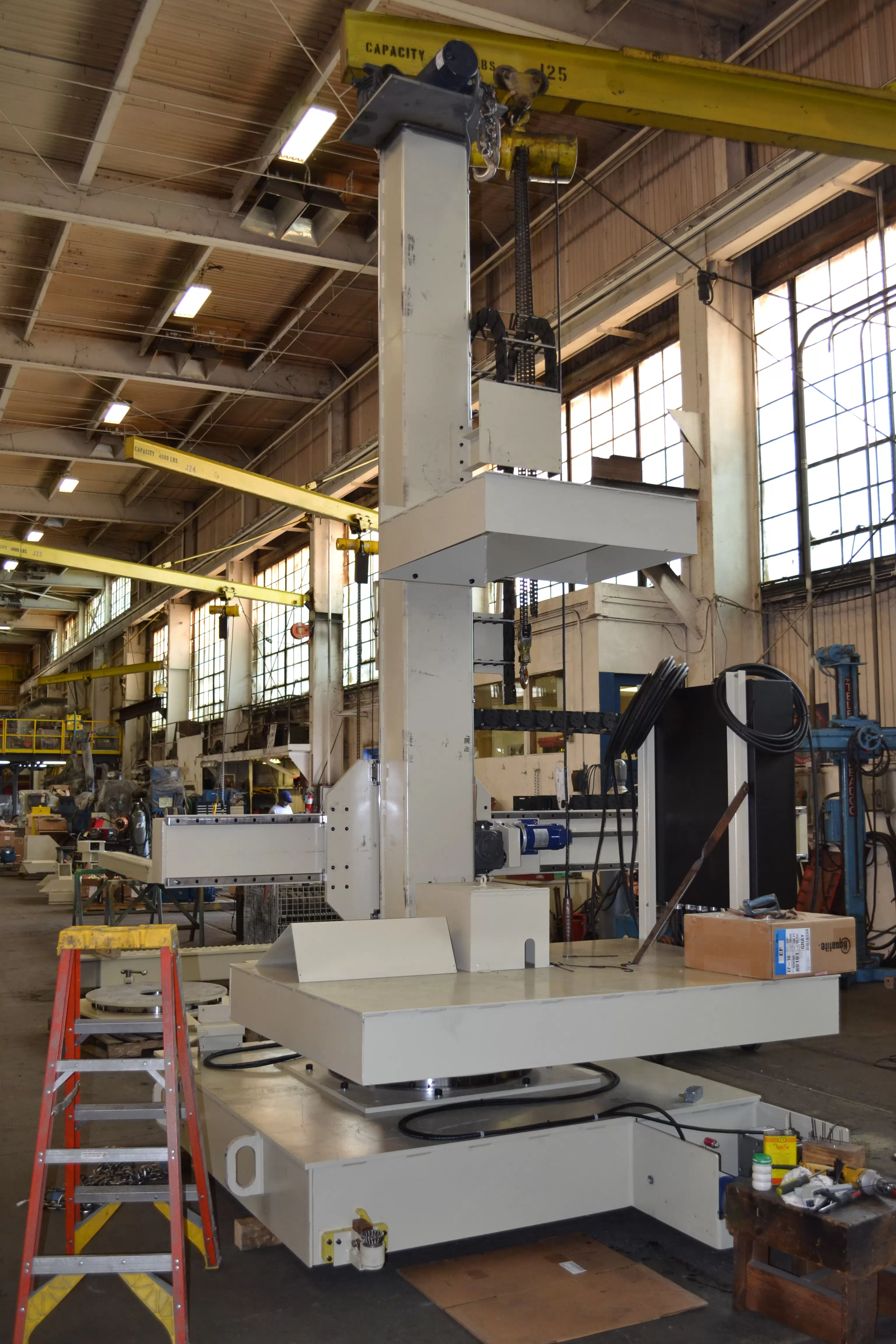
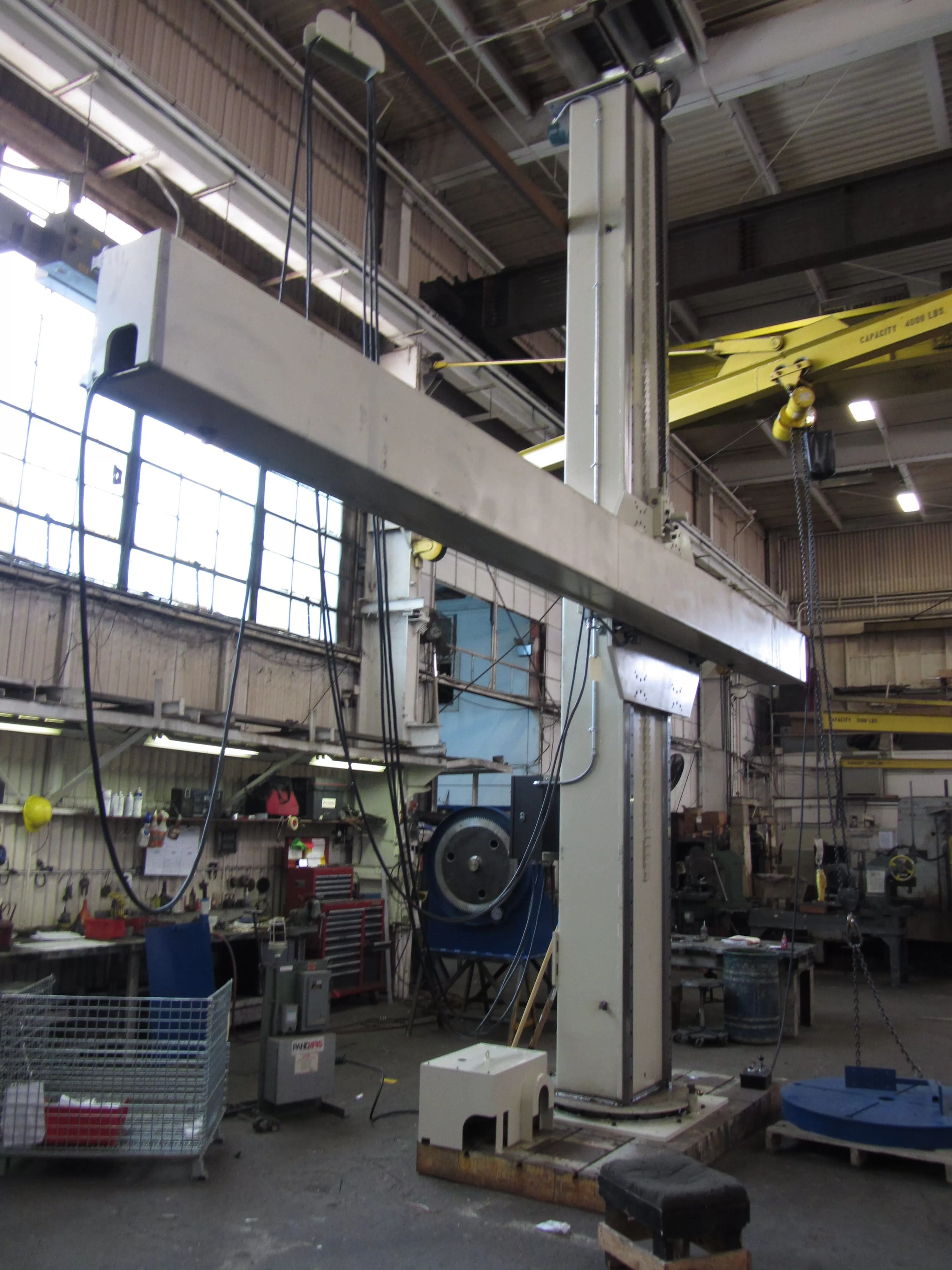
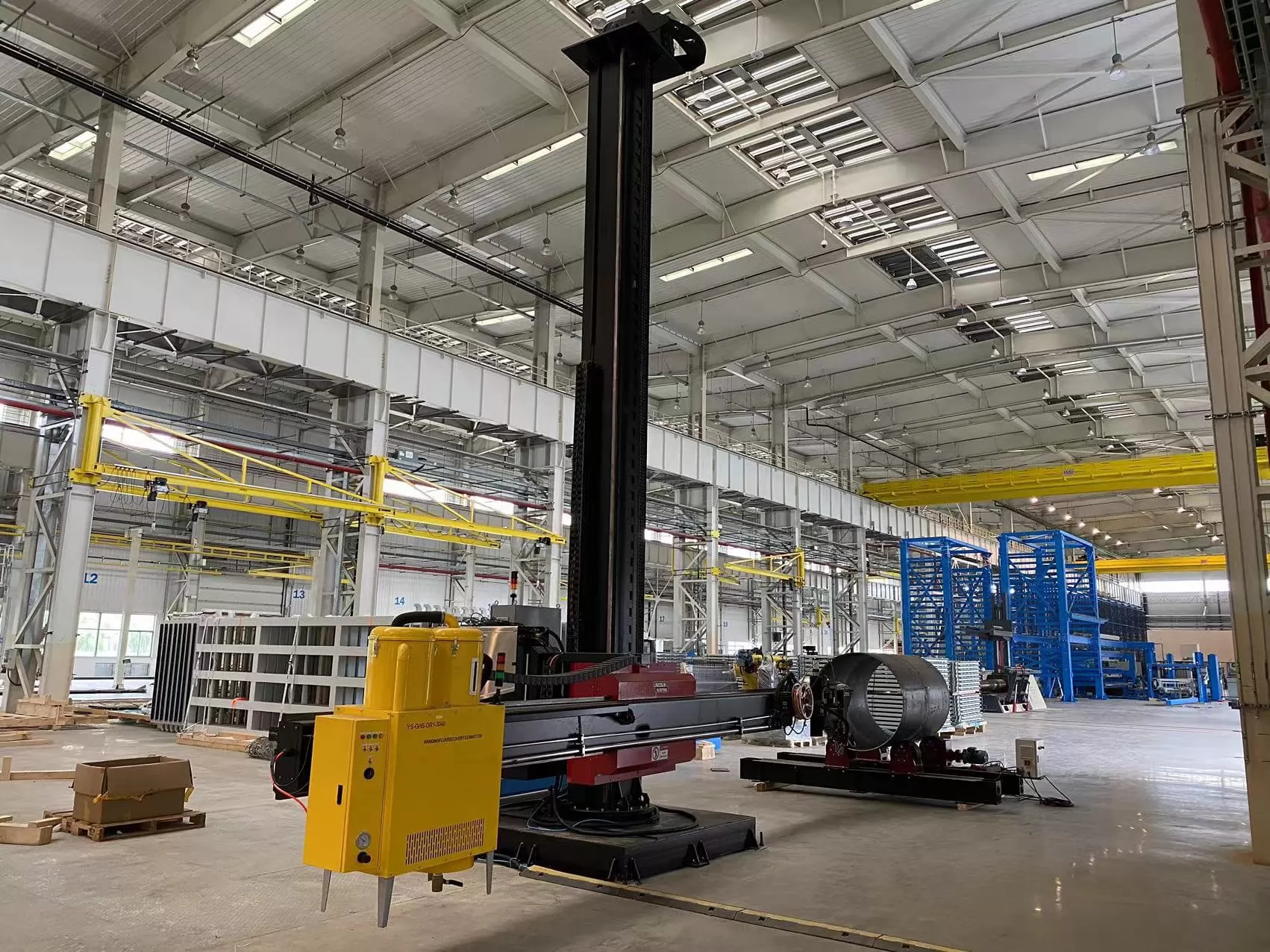
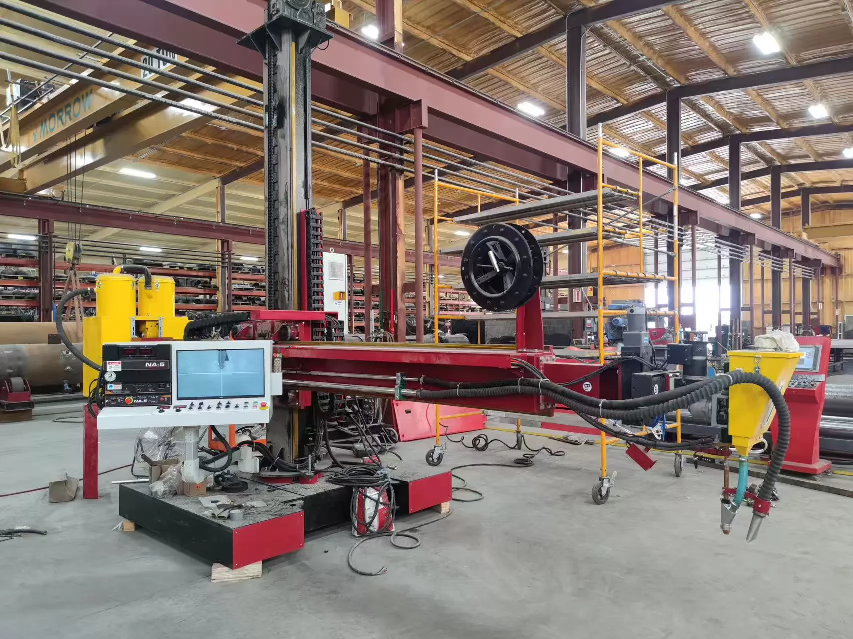
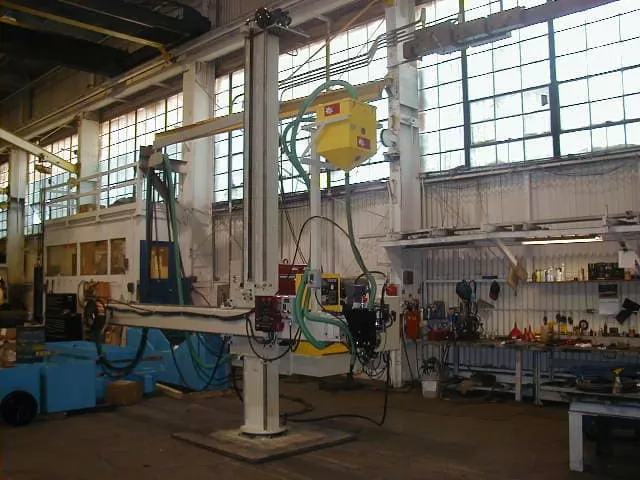
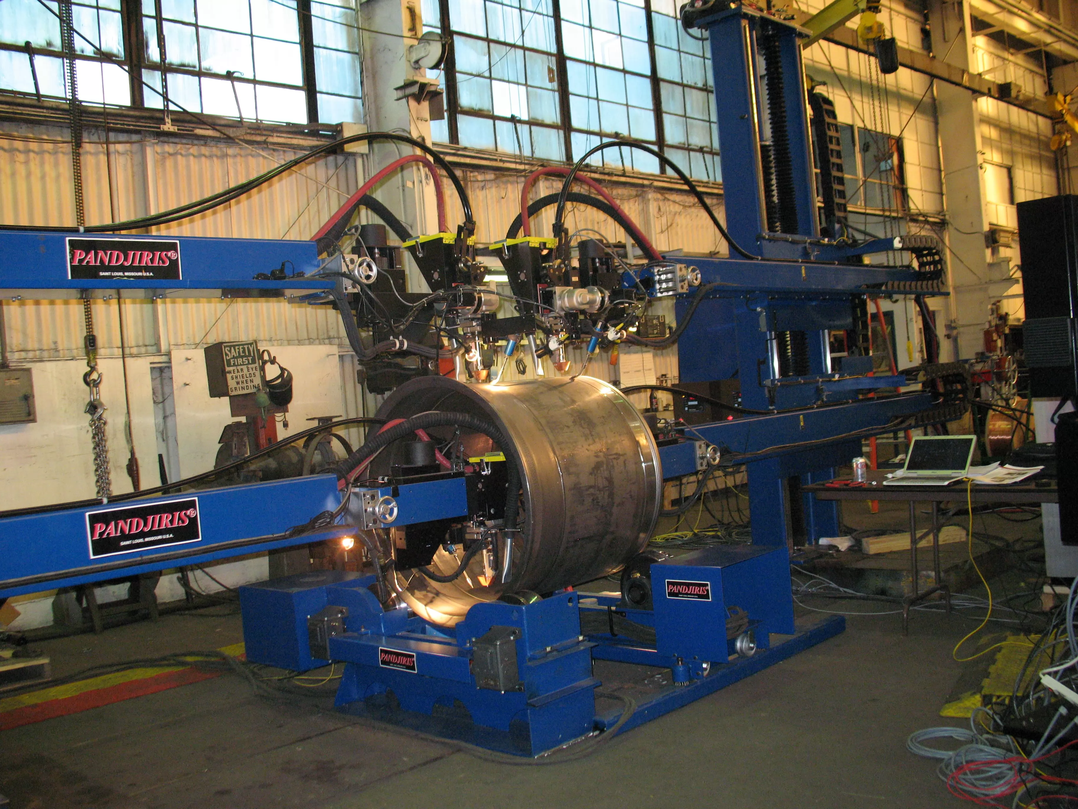
Column & Boom Systems — In the Field
Ready to Automate Your Welding Operation?
Talk to our engineering team about your column-and-boom welding manipulator requirements — standard or fully bespoke. No-obligation technical consultation and detailed quotation provided.