






Most enquiries for a welding manipulator machine open with a stroke figure — "we need a 5 × 6 m machine". That is usually the last thing to settle. The workpiece decides the machine: diameter and length, seam positions, head assembly weight, and whether one column serves one bay or three.
A welding manipulator machine carries the welding head along the joint on a vertical column and a horizontal boom. The workpiece stays put, or is turned beneath it by a welding rotator. That is what makes longitudinal and circumferential seams on vessels, tanks, pipe spools and large fabrications repeatable without re-rigging the part between passes.
This page is for specification and procurement, not first principles. It covers the four configurations MISA builds, how to build a working-range and load budget from your own workpiece, which processes and options change the specification, and the data a welding manipulator supplier needs to quote the right machine.
1. What a welding manipulator machine does
A welding manipulator machine is a head-positioning and travel system. A vertical column carries a horizontal boom that extends and retracts, with a cross slide at the boom end for fine torch adjustment. The head assembly — welding head, wire spool, flux hopper, camera and cabling — hangs at that end, while the workpiece stays put or is turned beneath it. The decisive distinction is which element moves: a manipulator moves the head, a rotator turns a cylindrical workpiece on driven rolls, and a positioner grips and tilts the part. §6 compares the three in detail.
The term is broader than one product: "welding manipulator" also describes small carriages and robot-mounted heads. MISA’s industrial range focuses on column and boom welding manipulators for large cylindrical and structural work — the machine class this buying guide covers. For structural mechanics and components, see the technical guide to column-and-boom systems; this page starts where that guide ends, at the purchasing decision.
A welding manipulator positions and moves the welding head, but the level of automation depends on the selected controls and the equipment integrated into the cell. Operators may be responsible for workpiece loading, set-up, parameter selection and process monitoring, while coordinated systems can automate selected movements and welding operations. Confirm the required operating mode and operator responsibilities when specifying the complete cell.
2. Configurations MISA builds
MISA offers light-duty and heavy-duty load classes, as well as fixed and motorized moving base configurations. These are two important factors in the selection process, but not every model is available in every combination. Confirm the available base type, load rating and working range for the specific model being quoted.
Load class follows the head assembly weight and working range; base type follows shop layout and the number of stations. Settling both early avoids ordering a large stroke on a column that cannot reach the second bay. The welding manipulator category page lists the published LH models with stroke, reach and load, and each model page states its base configuration.
| Configuration | Verified examples | Best fit | Plan for |
|---|---|---|---|
| Light Type | 150 × 150 mm cross slide, 100 kg class. LH-2020: 2 × 2 m, 100 kg; LH-2525: 2.5 × 2.5 m, 100 kg. LH-2020 offers fixed and motorized moving base options; confirm the LH-2525 configuration separately. | Smaller diameters, TIG or light MAG heads, one product family. | A SAW head with hopper and spool may exhaust the load budget before the workpiece does. |
| Heavy Duty Type | 200 × 200 mm cross slide, 200–300 kg class. LH-3535 3.5 × 3.5 m to LH-7080 7 × 8 m. | Large vessels, submerged arc heads, long seams, high arc-on hours. | Foundations, installation crane capacity, and a base matched to the stations. |
| Fixed Type | Column bolted to the floor; boom and cross slide travel. Manual or motorized revolve optional. Example: LH-3535 (base fixed). | One bay, one workpiece family, rotator does the turning. | Least civil work, but relocation means new anchors. Keep the swing radius clear. |
| Motorized Moving Type | Column travels on floor rails with pneumatic locking; revolve optional. LH-5060 5 × 6 m; LH-7080 7 × 8 m. | Several bays, or workpieces longer than any single boom reach. | Rail foundation, cable trench and a parking position outside traffic. Decide before the frame is ordered. |
Load is quoted at the boom extremity with the boom fully extended; stroke is vertical × horizontal. Load, stroke and base availability are all model-specific — confirm them on the current model page for the configuration being quoted.


Need a welding manipulator machine configured for your workpiece and welding process? Send MISA the drawing and head equipment list to settle load class and base type before a model is proposed.
3. How it works in a production cycle
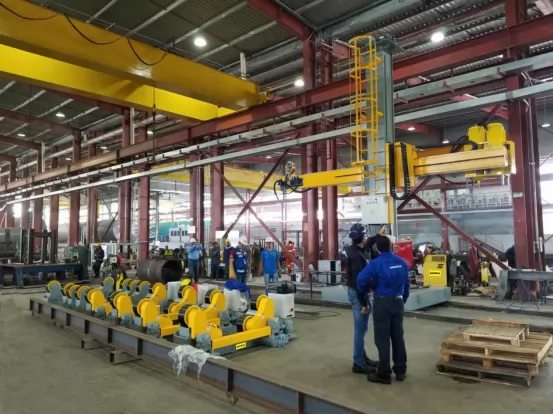
The workpiece is positioned first — on rotators for a cylindrical shell, on a fixture or the floor for a structural section. The boom is raised to seam height, extended until the head sits over the joint, and the cross slide makes the final alignment. A longitudinal seam is welded by travelling the boom along a stationary shell; a circumferential seam by holding the head while the rotator turns. Where the cell is configured for it, the control system coordinates the two so surface speed at the joint stays inside the process window.
Switching between seam directions on one workpiece is a configuration question — MISA lists a corner mechanism for changing the head between longitudinal and circular seams — and should be raised at enquiry stage. MISA also publishes running footage of these machines, a better check on travel smoothness than any datasheet figure.
4. Specifications that decide the purchase
4.1 Vertical stroke, horizontal reach and working envelope
These are three different measurements, and conflating them is the most common sizing error. Ask the supplier to state which one each figure on the quotation refers to.
- Vertical stroke is the column travel that sets the vertical range the head can reach. It is measured to the boom, not to the arc: the head assembly sits inside that budget, so 5 m of stroke is not 5 m of usable seam height.
- Horizontal reach starts with boom reach and cross-slide travel, but the usable figure also depends on the welding head and torch dimensions, their mounting position, and where the column can actually stand in the bay.
- Usable working envelope is the result of applying all of the above to the real workpiece: whether the arc can physically reach every seam on the drawing, at the highest and lowest positions, from that column location.
For an internal seam, reach depends on the column mounting position, vessel diameter, seam location and head dimensions — it is not a fixed addition of the diameter. Send the drawing and have the supplier plot the envelope rather than selecting a model row from diameter alone.
4.2 Boom load capacity
The load figure covers everything hung on the boom end: welding head, wire spool, flux hopper, camera, oscillator, brackets and cables — not just the torch. MISA quotes load at the boom extremity with the boom fully extended, so the published number describes the worst case; its LH range is published in 100 kg, 200 kg and 300 kg classes. That rating is a fixed, model-specific limit: fitting a heavier head does not change the rating, it consumes the payload budget available for the head assembly. Ask where a supplier measures its figure: a rating at mid-boom, or one excluding the hopper, is not comparable.
4.3 Travel speed control on a welding manipulator machine
Travel speed is set by the welding process, not by preference. Stable, finely adjustable speed across the usable range and repeatable starts and stops matter more than a headline maximum. MISA machines use VFD-controlled travel, and where a rotator is in the cell the two speeds must be matched to the joint’s surface speed.
Rated capacity and usable working envelope are not the same. The manipulator’s rated load remains a model-specific limit, but the available payload for the welding head and accessories must account for the complete equipment assembly. Likewise, nominal stroke does not guarantee that the welding arc can reach every seam. Check the actual working envelope against the head dimensions, mounting position and workpiece drawing.
4.4 Welding process compatibility
MISA’s category page lists SAW, MAG, GMAW and Force-TIG configurations, with tandem and narrow-gap welding as integration options. The process determines the head, wire feed, flux handling, cable set and control interface, so it changes the machine specification rather than adding an accessory. No single LH model should be assumed to support all four processes as standard: a light machine sized for a TIG torch is not automatically suitable for a submerged arc head with flux feeding and recovery. Confirm the process against the exact model and quotation.
4.5 Control system and verified options
MISA’s category page lists these as options, not as standard equipment on every LH model. The wired hand pendant (50 ft control cable) and the wireless hand pendant (300 ft working area) are published as alternatives; touch-screen and PLC control are described as available for special project requirements. Also listed: camera monitoring for SAW, MAG and TIG; a cross slide that can be programmed by PLC; a corner mechanism for switching the head between longitudinal and circular seams; and a flux recovery system with feeding, recovering, heating and screening for SAW setups. Oscillators and flux hoppers appear in MISA’s head-load checklist.
Every item above is subject to project configuration. Confirm in writing which options are included in the quotation, which control interface the cell controller will address, and whether the chosen combination is available on the model being quoted. A function listed for the range is not automatically fitted to a specific machine.

4.6 Welding manipulator machine specification worksheet
Fill this in before contacting a supplier. The right-hand column is the part most quotations omit, and it is the part that decides whether the machine fits the job.
| What you measure | What it decides | Your value |
|---|---|---|
| Largest diameter or width to reach; where the column can stand | Boom reach, plus cross slide and clearance | ____________ |
| Highest and lowest seam position, plus head assembly height | Usable vertical stroke | ____________ |
| Combined weight of head, spool, hopper, camera, oscillator, cables | Load class at full boom extension | ____________ |
| Seam types: longitudinal, circumferential, internal, external | Revolve, corner mechanism, travel direction | ____________ |
| Welding process and head model | Mount, flux handling, control interface | ____________ |
| Bays served, workpiece length, floor and crane limits | Fixed or rail-mounted base, rail foundation | ____________ |
| Rotator or positioner model already installed | Synchronisation interface and speed range | ____________ |
Have the worksheet filled in? Send it with your workpiece drawing to MISA. A configuration built from measured values is more useful than a catalogue model chosen from stroke alone.
5. Applications: what changes by industry
Application lists in brochures repeat the same benefits. What actually differs is the constraint that decides the machine.
Pressure vessels and boilers
Longitudinal and circumferential seams, inside and outside, must all fall inside one working envelope once head and cross slide are fitted. MISA’s published project records include manipulators on inner and outer circumferential seams alongside rotators and positioners, and SAW heads on boiler work; the vessel seam welding page shows the arrangement.
Storage tanks and large-diameter shells
Shell courses and long seams often exceed what a stationary column covers, which is where a rail-mounted base earns its cost; where the work stays in one bay, a fixed base avoids the civil work. Not every configuration suits both internal and external seams.
Pipe spools and heavy fabrications
For pipe work the constraint is synchronisation — tell the supplier which rotator is installed, since MISA agrees the manipulator–rotator control interface at quotation stage rather than retrofitting it after delivery. For girders and fabricated sections it is long horizontal travel rather than revolve or tilt; lighter compact components sit at the other end of the range, where a light-type machine is the correct answer.

6. Manipulator vs rotator vs positioner
These three are regularly confused in enquiries, and ordering the wrong one is expensive. The distinction is which element moves, and — between rotator and positioner — how the workpiece is driven.
| Machine | What moves | How the workpiece is driven | Role in a cell |
|---|---|---|---|
| Welding manipulator | Torch, on a column and boom | Workpiece stationary, or turned by another machine | Positions and travels the head along the joint |
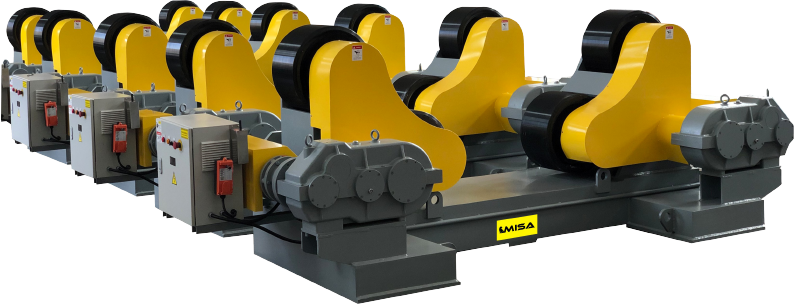
| Welding rotator | Workpiece, supported and rotated | By friction between the outside diameter and driven rolls | Turns cylindrical shells for circumferential seams |
| Welding positioner | Workpiece, gripped and tilted | Positively, via faceplate, chuck or between centres | Brings short or non-cylindrical joints into a flat position |
In an integrated cell the manipulator and rotator are specified as a pair, because rotation speed and head travel must agree at the joint. A positioner is used when the workpiece needs controlled rotation or tilting to improve weld access, particularly for asymmetric, non-cylindrical or difficult-to-fixture parts. The three are complementary, not alternatives; settle the control interface and speed range at order stage.


7. How to choose the right welding manipulator machine
The sequence matters. Skipping a step usually means changing the model later.
Step 1 — Establish the workpiece envelope
Record diameter, length, wall thickness and weight, plus a drawing showing every seam. Include internal seams: they change reach more than diameter does.
Step 2 — Define seam types and positions
Longitudinal, circumferential or both; inside or outside. This decides travel direction, whether the column must revolve, and whether a head-change mechanism is worth specifying.
Step 3 — Build the working-range budget
Apply the three measurements in §4.1 to the drawing: usable vertical stroke, horizontal reach including cross slide and head dimensions, and clearance to every seam position. This gives the working envelope, not catalogue stroke.
Step 4 — Select load class and base
Weigh the complete head assembly to choose light or heavy duty, then decide fixed or rail-mounted from the number of bays and workpiece length. Treat them as two separate checks, and confirm that the resulting combination is available on the model being quoted.
Step 5 — Confirm process and equipment compatibility
Name the process, head model, power source and consumables; confirm the mount, flux handling, cable set and control interface for that exact combination.
Step 6 — Check the workshop
Floor loading and rail foundation, crane capacity for installation, overhead clearance, cable routing and a parking position for a travelling column. Rail work is civil work.
Step 7 — Allow for future work
If the product mix will change, say so. Custom configurations are developed against a workpiece drawing, and interfaces for later automation are far cheaper at build time.
Workpiece diameter and length · maximum weight · welding process and head model · seam types, internal and external · required working height and boom reach · desired automation and control level · head equipment list with weights · rotator or positioner model already installed · site supply voltage and space constraints · certification requirements for the destination market.
8. How to evaluate a welding manipulator supplier
Price comparisons are only meaningful once the specifications are comparable. Evaluate the supplier on what it can put in writing.
- Relevant manufacturing experience with this machine class, and references for comparable workpiece sizes.
- Range and custom engineering — whether the configuration is developed from your drawing and both base types are genuinely available.
- Per-model documentation stating how load, stroke and speed are defined and which options are included in the price.
- Integration capability with your rotators, positioners and power sources, including the control interface and responsibility for commissioning the cell.
- Quality control and testing before shipment, and the inspection or compliance documentation applicable to your model and market.
- Installation, commissioning, training and spare parts — what is supplied, what is chargeable, and what must be on site before delivery.
Two suppliers can quote the same stroke and load and describe different machines. Ask where load is measured, what stroke is measured to, and which head equipment the rating assumes. A supplier that answers those three in writing is usually the one that can build the machine.
9. MISA welding manipulator machine solutions
MISA builds column and boom welding manipulators in light and heavy-duty load classes, on fixed and motorized moving bases. Published models run from 2 × 2 m at 100 kg through 7 × 8 m at 300 kg; the process and control options are described in §4 and are configured per project.
Verified examples: the LH-2020 (2 × 2 m, 100 kg, fixed and motorized moving base options), LH-3535 (3.5 × 3.5 m, 200 kg, fixed base with optional revolve), LH-5060 (5 × 6 m, 200 kg, motorized moving with pneumatic locking) and LH-7080 (7 × 8 m, 300 kg, motorized moving). The welding manipulator category page carries stroke, reach and load for the full LH range.
MISA publishes the installations behind its machines. The examples below are drawn from that project record, not from general claims about the product range:
| Year / site | Equipment listed as supplied | Application recorded |
|---|---|---|
| 2018 · Singapore | 2 × LH-5050 manipulators | Inner and outer circumferential seams, fillet welds and longitudinal seams with rotators and positioners |
| 2019 · Mersin, Turkey | 2 × LH-5070 manipulators with Lincoln DC-1000 SAW systems | Outer seam and inner ring seam on boiler and petrochemical work |
| 2020 · Perth, Australia | 5 m × 10 m manipulator with 2 sets of 80 t self-aligning rotators | Pipeline fabrication |
| 2022 · Monterrey, Mexico | 3 × LH-4060 manipulators with 5 sets of 10-ton self-aligning turning rolls | Aluminium welding on oil tanks |
| 2023 · Montreal, Canada | LH-4040 column and boom on a 30 t fit-up growing line with Aotai MZ-1000 SAW | A manipulator integrated into an automated pipe line |
| 2023 · Dammam, Saudi Arabia | LH-4040 manipulator with 10 sets of 10-ton conventional rotators | Water tank production |
These are project-specific configurations, not catalogue rows: a model number in a project record does not define a standard specification. Third-party welding power sources, rotators and positioners named above are recorded as equipment used alongside the manipulator on that project, not as MISA-manufactured products, and the recorded outcomes are not general performance guarantees. Full write-ups are on the vessel seam welding case page, with more installations under project presentation.
Custom strokes, head mounts and control interfaces are developed against the workpiece drawing. For straight seams see the longitudinal seam welding machine range.
10. Frequently asked questions
What is a welding manipulator machine used for?
It positions and travels a welding head along a joint using a vertical column and horizontal boom, for longitudinal and circumferential seams on pressure vessels, tanks, pipe spools and large fabrications. A welding rotator usually turns the workpiece. It can reduce repeated workpiece repositioning and help maintain a more consistent welding head path, depending on the workpiece handling and equipment configuration.
What is the difference between a welding manipulator and a welding positioner?
A manipulator moves the head while the workpiece stays put. A positioner grips the workpiece on a faceplate or chuck and rotates and tilts it to bring the joint flat. They solve different problems and are often used together; a rotator is a third machine that turns cylindrical work on driven rolls.
Which welding processes can a welding manipulator support?
MISA lists SAW, MAG, GMAW and Force-TIG configurations, with tandem and narrow-gap welding as integration options. The process determines head, wire feed, flux handling and control interface, so it must be stated before the machine is configured. A machine built for a light TIG torch is not automatically suitable for a submerged arc head.
How do I select the correct welding manipulator capacity?
Work from two budgets. Add the complete head assembly weight — head, spool, hopper, camera, oscillator, cables — to choose the load class at full boom extension. Then add the head and cross slide envelope to the highest and lowest seam positions for usable stroke and reach. MISA quotes load at the boom extremity with the boom fully extended; confirm the definition for the model being quoted.
Can a welding manipulator work with a welding rotator?
Yes, and it is the normal arrangement for circumferential seams on cylindrical shells. The rotator turns the workpiece and the manipulator holds or travels the head. The control system can be configured to coordinate them, but the interface and rotator speed range must be agreed at quotation stage — tell the supplier which rotator model is installed.
Specify from the workpiece, not the model number
The fastest route to a correct quotation is a workpiece drawing plus six figures: diameter and length, maximum weight, welding process and head model, seam types, required working height and boom reach, and the automation level you need.
- Sources for this guide. All model specifications, control options and project records quoted above are taken from MISA’s own published pages: the column and boom welding manipulator category page, the individual LH model pages, the vessel seam welding case page and project presentation. Welding codes and standards are deliberately not cited here: they govern the welding procedure and the destination market, not the specification of a welding manipulator machine. Confirm the current specification and any applicable certification requirements with MISA before ordering.